212 Series Tooling Alcoa Fastening Systems
13
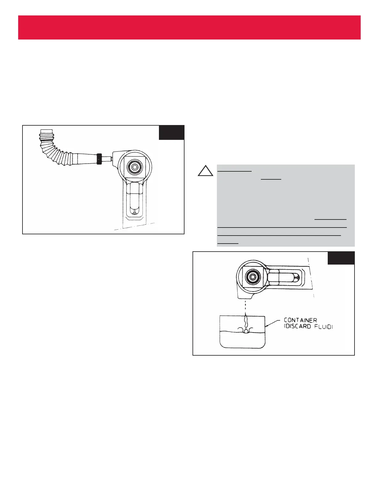
Fig. 3.2
Fig. 3.3
FILLING AND BLEEDING PROCEDURE (CONT.)
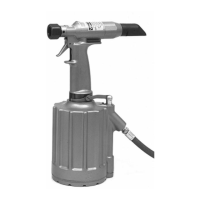
5. Stand tool upright on bench. While triggering
tool slowly (20 - 30 cycles), bend fill bottle at
right angles to tool- - see FIGURE 3.2. Air
bubbles will emerge from tool. When bubbles
stop, cycling may be discontinued.
6. When trigger is released, pull piston returns
to idle position (full forward). Disconnect tool
from airline.
7. Lay tool on its side. Remove fill bottle. Top
off fluid in fillport. Install bleed plug and
tighten.
8. Connect airline to tool. There is a choice of
two procedures for measuring the stroke - -
with and without a stall-nut - - see appropri-
ate section and follow the selected procedure.
If stroke is less than specified, remove bleed
plug and top off fluid. Reinstall bleed plug.
9. Increase air pressure to specification. Install
two fasteners to check function and installation
in a single stroke, or cycle tool with stall-nut
fully threaded onto piston to load up tool.
Measure stroke again. Remove plug and top
off fluid. Reinstall plug and cycle again - -
measure again. Continue this process until
stroke meets minimum requirements,
Bleed Procedure for Partially Filled Tool in
Field Use - - as Applicable:
1. Disconnect tool from airline. With fillport
facing up, lay tool on its side.
2. Remove bleed plug from bleed port.
3. Hold tool over suitable container with fillport
facing into container.
4. Connect tool to airline. cycle tool several times
to drain the old fluid, air and foam.
5. Screw fill bottle into fillport.
6. See warning above. With air pressure set at 20
- 40 psi, connect airline to tool
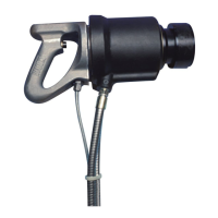
WARNING
Air pressure MUST be set to 20- 40 psi
to prevent possible injurious high pres-
sure spray. Never cycle tool without
bleed plug tightened, fill bottle tightened
in the tool, or the fillport held over a
receptacle (see FIGURE 3.3). When not
properly contained any fluid present in
tool will spray out. Severe injury may
result.
 Loading...