4
532551-3_A
SIDE IMAGING® PLASTIC THRU-HULL TRANSDUCER
4
|
Attach the Transducer
1. Feed the transducer cable through the drilled hole, then temporarily install the transducer to
check the fit.
2. Apply a generous amount of marine-grade silicone sealant or slow-curing epoxy inside the
drilled hole and along the mating surfaces of the transducer housing and leveling block.
3. Proceed to the instructions that correspond with your installation type (control head model)
and transducer orientation.
SOLIX Series
1. Make sure the rounded end of the transducer is facing the bow, pointing forward, and parallel
to the centerline.
2. Insert the transducer into the drilled hole from outside the boat with the leveling block(s)
installed according to your installation type.
3. Hold the shroud horizontally with the inside teeth facing up. Thread the cable connector through
the shroud. See the illustrations below.
4. Fit the split nut pieces to each other with the cable in the center. The ridged side of the split
nut should face down.
5. Slide the split nut into the shroud so that the assembly is flat. Install the two screws into the
shroud holes to secure the assembly. Hand tighten only.
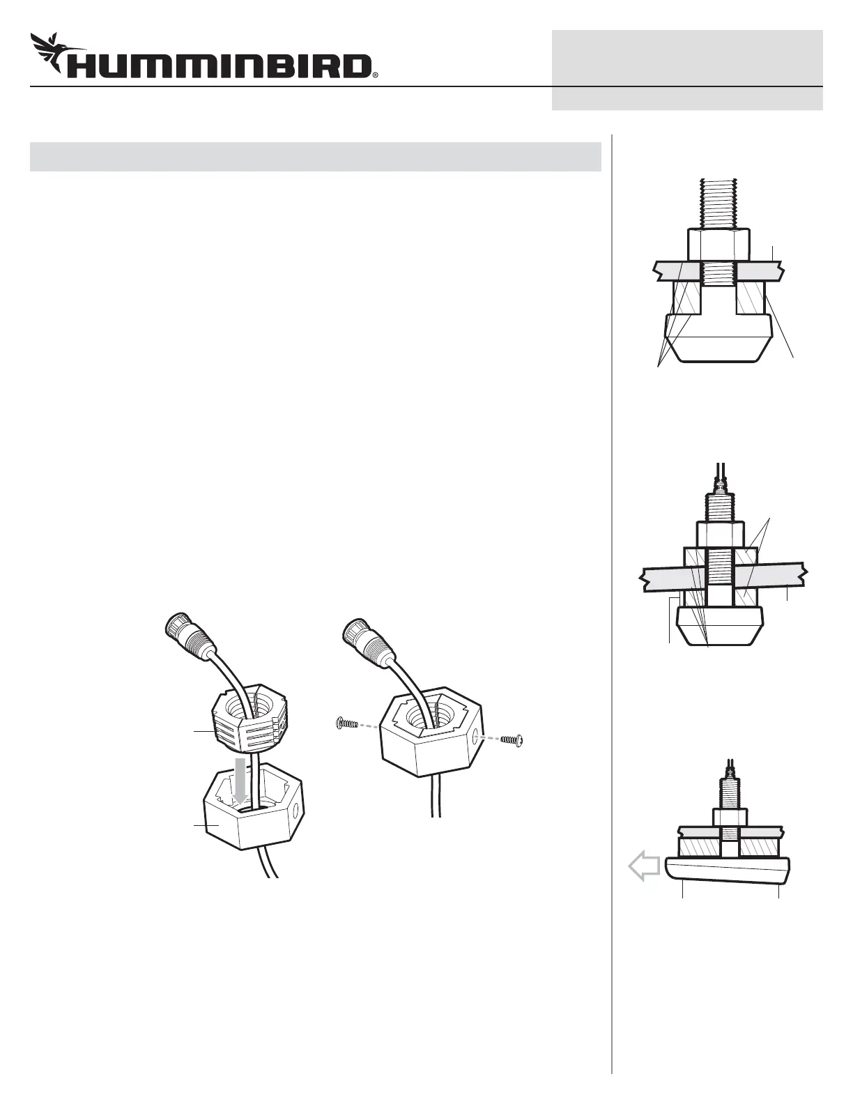
SOLIX Series
Inserting the Split Nut into the Shroud Installing the Screws
split nut
shroud
HELIX Series
1. Make sure the rounded end of the transducer is facing the bow, pointing forward, and parallel
to the centerline.
2. Insert the transducer into the drilled hole from outside the boat with the leveling block(s)
installed according to your installation type, then install the nut onto the threaded stem from
inside the boat.
leveling block
(uncut)
hull
Apply marine
adhesive sealant to
all mating surfaces
Standard Installation
(Flat Hull)
cut leveling
blocks
hull
Apply marine adhesive
sealant to all mating
surfaces
1/8" (3 mm)
minimum
thickness
Alternate Installation
(Deadrise greater than 2°)
rounded end
facing the bow
of the boat
square end facing
the stern of the
boat
Correct Orientation of the
Transducer