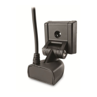
Bronze Thru-Hull Transducer
1
Thank You
Thank you for choosing Humminbird®, America's #1 name in fishfinders. Humminbird® has built its reputation
by designing and manufacturing top-quality, thoroughly reliable marine equipment. Genuine Humminbird®
accessories offer the opportunity to upgrade and expand the capabilities of your Humminbird® product.
Your Humminbird® is designed for trouble-free use in even the harshest marine environment. In the unlikely
event that your Humminbird® does require repairs, we offer an exclusive Service Policy - free of charge
during the first year after purchase, and available at a reasonable rate after the one-year period. For
complete details, see the Warranty section included in this manual.
Installation Overview
Following are instructions for the installation of this accessory. Before you start installation, we encourage
you to read these instructions carefully in order to get the full benefit from your Humminbird® accessory.
NOTE: This type of transducer installation is not recommended for trailerable boats.
NOTE: This transducer requires drilling a hole in the hull of the boat; therefore, installation should be performed
by a qualified marine technician.
In addition to the hardware supplied with your transducer, you will need a drill, a small drill bit for a pilot
hole, a hole saw to fit the threaded stem of the transducer, a large adjustable wrench, a level, and marine-
grade silicone sealant.
Installation
Perform the procedures in the following sections to install the transducer on your boat.
1. Testing the Transducer Prior to Installation
Prior to installation, test the transducer to make sure that no damage occurred during shipping.
1. After connecting the transducer to the fishfinder, hold the transducer in the water over the side of the boat
to confirm proper operation. If the transducer is working properly, you should be able to see the bottom on
the control head display. The bottom image should be relatively strong and there should be detailed structure
on the display.
2. Locating the Transducer Mounting Position
Outside the boat, the best location for the transducer will be aft midship, as close to the centerline of the
boat as possible. The transducer should be mounted forward of the propellers on inboard boats, and
separated adequately from other transducers, strakes, rivet lines, or other protrusions. Make sure that there
is nothing in front, behind, or to the side of the transducer that is closer than 12".
Inside the boat, there must be room to access the mounting location for installation and cable routing.
Thru-Hull Installation
Deadrise Angle
Areas of Possible Turbulence
Rivets Strakes
Transom Hull
Preferred Mounting Location
Bronze Thru-Hull Transducer
2
530513-2_C
Deadrise: Another consideration is the angle of deadrise. The transducer, when mounted, should point straight
down. If the selected mounting location has a hull deadrise of 8 degrees or greater, a leveling block should be
used to level the transducer housing and direct the sonar signal straight down. If you need to use the leveling
block, make sure that the inside surface of the hull is smooth enough to seat the leveling block securely.
NOTE: If the included transducer will not work for your application, you may exchange it, NEW and
UNASSEMBLED, with mounting hardware included, for a transducer appropriate for your application - often at
very little or no charge depending on the transducer.
3. Attaching the Transducer
Before attaching your transducer, you will need to decide which type of installation to use:
• For a standard installation, where the deadrise is less than 8 degrees, you do not need to use a leveling
block because the transducer will be mounted directly to the hull; drill the hole perpendicular to the hull.
• For an installation where the deadrise is greater than 8 degrees, use a suitable leveling block (not
included), cut at the appropriate angle, to compensate for the deadrise. Drill the hole perpendicular to
the waterline.
1. From the outside of the hull, drill a small pilot hole (smaller than the centering bit of your drill bit or hole
saw), at the mounting location you selected in procedure 2.
CAUTION: Before you drill, make sure you are drilling in the correct orientation according to the installation
guidelines above.
2. Use the pilot hole (from the outside of the hull) to drill a hole sized to fit the threaded stem of the
transducer:
NOTE: If you are mounting the transducer body directly to the hull, drill the hole perpendicular to the hull.
NOTE: If you are using a leveling block, drill the hole perpendicular to the waterline.
3. Thoroughly clean and deburr the drilled hole and clean the outside of the hull.
4a. If you are not using a leveling block, skip to step 5.
OR...
4b. If the hull angle is greater than 8 degrees, you should use a leveling block (not included) to level the
transducer. The block (usually made of wood) should be cut to match the angle of the deadrise of the hull.
You should cut the leveling block into two equal pieces: one which mounts outside the hull and is shaped
to match the profile of the transducer, and one which mounts inside the hull and provides a level surface
for the fasteners. The thinnest wall of the outside level block must be at least 1/8".
NOTE: A separately-purchased fairing block can also be used to create a hydrodynamic waterflow around the
transducer body. A fairing block is required for round body transducers as well. The design and fabrication of this
block varies greatly with different hull shapes; therefore, it should be customized by a qualified marine technician.
5. Feed the cable through the hole, then temporarily install the transducer to check the fit.
NOTE: If the transducer is round it may have a notch on the housing and stem which indicates the forward side
of the transducer. This type of transducer is directional in nature and must be aligned with the front of the boat
(the direction of travel). Failure to align the transducer notches with the front of the boat will result in
incorrect bottom readings and incorrect fish locations.
Leveling Block Assembly to Hull
Leveling
Blocks
Hull Cross
Section
Transducer
Housing
Attaching the Transducer
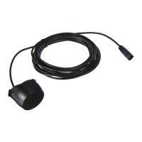
Extension
Cable
Transducer
Cable
Nut
Hull Cross
Section
Align
notches
with the
front of the
boat, if applicable
Transducer Housing