Do you have a question about the Humminbird PIRANHAMAX 4 and is the answer not in the manual?
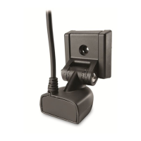
Arrange parts and assemble the Transducer onto the Mounting Bracket.
Use the Transducer Template to mark the mounting bracket location 12 inches from the Keel.
Drill a pilot hole approximately 1 inch into the Transom using a 9/64” Drill bit.
Use marine grade Silicone to seal the pilot holes before installing the Mounting Bracket.
Install the Mounting Bracket onto the Transom using supplied hardware, mounting transducer highest.
Route Transducer wire vertically, mark clip locations, drill, apply silicone, and install Wire Clips.
The Piranhamax 4 Transducer is a device designed to enhance your boating experience by providing essential information about the underwater environment. This install guide, WB.TD.01, outlines the steps for properly setting up and maintaining your transducer, ensuring optimal performance and longevity.
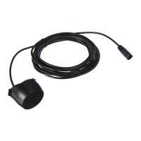
The Piranhamax 4 Transducer serves as the "eyes" of your boat, sending and receiving sonar signals to detect underwater objects, fish, and the contours of the seabed. This information is then processed and displayed on your boat's fish finder or depth sounder, allowing you to navigate more safely, locate fishing spots, and understand the aquatic terrain beneath your vessel. By providing real-time data, the transducer helps you make informed decisions while on the water, whether you're fishing, cruising, or exploring new areas. Its primary function is to provide accurate and reliable underwater readings, which are crucial for both recreational and professional boaters. The device is engineered to withstand marine environments, ensuring consistent performance even in challenging conditions.
The installation process for the Piranhamax 4 Transducer is designed to be straightforward, though it requires careful attention to detail to ensure proper function. Before beginning, it is crucial to select the correct transducer template that matches your Piranhamax 4 transducer and boat model. This initial step is highlighted as an "ATTENTION" point, emphasizing its importance for a successful installation.
The installation process is broken down into several steps, each with clear instructions and accompanying visual aids.
The first step involves arranging all parts and hardware. The transducer must be assembled onto its mounting bracket. It is important to refer to the supplied manufacturer's instructions for full assembly steps, as these provide detailed guidance on putting the components together correctly. This ensures that the transducer is securely attached to its bracket, ready for mounting on the boat.
Once the transducer is assembled, the next critical step is to determine its precise installation location on the boat's transom. Using the proper transducer template, you will mark the installation spot for the mounting bracket. A key instruction here is that the installation location should be 12 inches from the keel. This measurement is crucial for optimal performance and is also highlighted as an "ATTENTION" point, reinforcing the importance of accurate placement. The template helps ensure that the transducer is positioned correctly to provide clear and consistent readings.
After marking the location, a pilot hole needs to be drilled into the transom. A 9/64” drill bit is specified for this task, and the hole should be drilled approximately 1” into the hull. Before drilling, an "ATTENTION" warning advises ensuring that no cords or fuel separators are at risk of being damaged. In some boat models, it may be necessary to remove carpeting or flotation foam to access the drilling area safely. This step underscores the need for caution and preparation to avoid damaging existing boat components.
To prevent water intrusion and ensure the longevity of the installation, marine-grade silicone must be applied to seal the pilot holes before installing the mounting bracket. This step is vital for protecting the boat's hull from water damage and maintaining the integrity of the installation. The silicone creates a watertight seal, preventing moisture from entering the transom.
With the pilot holes sealed, the mounting bracket can be installed onto the transom using the supplied hardware. It is important to mount the transducer in the highest possible position. This positioning helps to minimize drag and ensures that the transducer is less susceptible to damage from impacts with underwater objects. Proper installation at this stage is key to the transducer's stability and performance.
The final step involves routing the transducer wire vertically along the transom. As the wire is routed, the locations for each wire clip should be marked. Pilot holes are then drilled into the transom at these marked locations, silicone is applied to seal them, and the wire clips are installed to secure the cable. This ensures that the wire is neatly organized, protected from damage, and does not interfere with other boat operations. Proper wire management is essential for both aesthetics and the long-term reliability of the transducer's connection.
The installation process requires a specific set of tools, which are clearly listed to help users prepare:
While the manual primarily focuses on installation, the emphasis on using marine-grade silicone and securing the wire properly implies a design for durability and ease of maintenance. The use of silicone ensures a watertight seal, which is a critical maintenance feature as it prevents water ingress that could lead to hull damage or electrical issues. Properly routed and clipped wiring protects the cable from wear and tear, reducing the likelihood of signal loss or damage.
The design of the mounting bracket, allowing the transducer to be mounted in the "highest position," also contributes to its maintenance by minimizing exposure to potential impacts from debris or shallow water, thereby reducing the need for repairs or replacements. Regular inspection of the silicone seals and wire clips would be a good practice to ensure the integrity of the installation over time. Should the transducer need to be removed for cleaning or replacement, the installation method suggests a relatively straightforward process, provided the original steps are followed in reverse. The robust construction implied by the installation steps suggests that the Piranhamax 4 Transducer is built to withstand the rigors of the marine environment, requiring minimal ongoing maintenance beyond routine checks.
| Sonar Frequency | 200/455 kHz |
|---|---|
| Power Output | 300 Watts (RMS) |
| Depth Capability | Up to 600 feet |
| Compatibility | PIRANHAMAX 4 |
| Beam Angle | 28° and 16° |
| Sonar Coverage | 28°, 16° @ -10dB |