EasyManua.ls Logo

Humminbird APEX Series User Manual

Humminbird APEX Series
19 pages
To Next Page IconTo Next Page
Page #1 background imageLoading...
Page #1 background image
1
532508-4_A
TRANSOM TRANSDUCER Installation Guide
The transom mount installation allows adjustment of both running angle and depth after the
transducer is mounted, which enables you to tune the installation for best results. It is important
to read the instructions completely and understand the mounting guidelines before beginning this
installation.
NOTE: Due to the wide variety of hulls, only general instructions are presented in this guide. Each
boat hull represents a unique set of requirements that should be evaluated prior to installation.
For detailed information about installing transducers on different hull types, download the
Transducer Installation Resource Guide from our Web site at humminbird.com.
NOTE: Your transducer may not look exactly like the transducer shown in the illustrations, but it
will mount in exactly the same way.
I P
Install the control head before you start the transducer installation. See the control head
installation guide.
Review your boat manufacturer’s owner’s manual
for recommended transducer installation
locations and cable routing methods, as well as your transom and/or deadrise angle.
Read and understand your boat’s warranty
before starting this installation.
Visit our Web site at humminbird.com for additional information and resources for transducer
installations. Also, visit youtube.com/humminbirdtv for informational videos.
Confirm your boat is level for the installation.
Consider your speed requirements.
Traveling over 65 mph with the transducer in the water is not recommended with the
transom mount transducer, as damage may occur. If speed above 65 mph is critical, see the
FAQ (Frequently Asked Questions) section of our Web site at
humminbird.com.
Supplies:
In addition to the hardware supplied with your transducer, you will need a powered
hand drill and various drill bits, various hand tools, including a ruler or straightedge, a level,
marker or pencil, Phillips-head screwdriver, flat head screw driver, a socket/nut driver, a 1/2"
(13 mm) wrench and torque wrench, safety glasses and dust mask, marine-grade silicone
sealant, and dielectric grease (optional). You may also need extension cables and hardware for
routing the cable to the control head.
I O
New Installation: Review Turbulence-Free Mounting Guidelines and proceed to section 1. Mount
the Transom Bracket to the Boat.
Previously-installed Transducer: If you have a previously-installed XHS transducer on the transom,
the bracket in this installation kit can be installed in the same location using the following
instructions:
1. Line up the metal bracket with the previously-used mounting holes to confirm that the two slot
holes match the previous installation. Fill any unused holes with marine-grade silicone sealant.
Question and Answer IconNeed help?

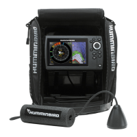
Do you have a question about the Humminbird APEX Series and is the answer not in the manual?

Humminbird APEX Series Specifications

General IconGeneral
CompatibilityHumminbird APEX Series fish finders
Frequency1.2 MHz
Power Output1 kW (depending on transducer)
Transducer TypeCHIRP, Side Imaging, Down Imaging
BeamwidthVaries by model (e.g., 20° at 83 kHz, 10° at 200 kHz)

Summary

INSTALLATION PREPARATION

Gather Installation Supplies

List of necessary tools and materials for transducer installation.

INSTALLATION OVERVIEW

New Installation Procedure

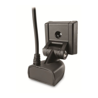
Steps for a new installation, starting with mounting the bracket.

Previously-Installed Transducer

Guidance for replacing a previously installed transducer.

TURBULENCE-FREE MOUNTING GUIDELINES

Avoid Turbulent Water Areas

Locate transducer away from ribs, strakes, or propeller turbulence.

Consider Propeller Rotation Direction

Account for propeller wash direction to minimize turbulence.

Maintain Distance from Propellers

Ensure adequate distance, at least 15 inches, from boat propellers.

Ideal Mounting Location Considerations

Choose location right of propeller, avoiding trailer bunks or rollers.

Stepped Hull Mounting

Mount on a step for stepped hulls, avoid mounting behind a step.

Maintain Parallel Alignment

Mount transducer parallel to the waterline, fully submerged.

Side Imaging Obstruction Check

Ensure no obstructions block Side Imaging beams for clear view.

Mount the Transom Bracket to the Boat

Bracket Placement and Leveling

Position and level the bracket on the transom, marking drill holes.

Drill Mounting Holes

Drill three holes to the specified depth, ensuring perpendicularity.

Secure Transom Bracket

Fill holes with sealant and attach bracket loosely with screws.

Install the Transducer

Attach Transducer to Bracket

Align transducer bracket, install screws and washers, hand tighten.

Align Transducer Bracket to Transom Bracket

Connect transducer bracket to transom bracket, hand tighten.

Secure Transducer Assembly

Install pivot bolts, washers, and lock nuts; tighten hardware loosely.

Confirm the Mounting Angle

Adjust Transducer Height

Adjust bracket height to ensure submersion and avoid jet stream.

Adjust Transducer Angle

Set transducer parallel to boat hull with a slight 5-degree down angle.

Hand-Tighten Pivot Bolts

Hand-tighten pivot bolts to finalize angle adjustments.

Route the Cable

Cable Routing Methods

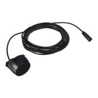
Route cable over transom or through a hole, keeping it away from damage.

Manage Cable Slack and Excess

Allow slack for movement, coil excess cable to reduce interference.

Cable Routing Precautions

Avoid sharp bends, do not shorten cable, route away from other cables.

Connect the Cable

Connect Transducer to Control Head

Connect transducer cable to the control head port, hand-tighten connector.

Test and Finish the Installation

Prepare for Testing

Ensure control head, transducer, and cables are installed and routed.

Perform Sonar View Test

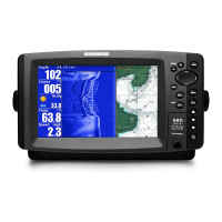
Turn on control head, select Sonar View, check for bottom detection.

Perform Side Imaging Test

Select Side Imaging View and navigate to check beam clarity.

Finalize Transducer Tightening

Confirm bracket level and fully tighten pivot bolts to specified torque.

MAINTENANCE

Cleaning the Transducer

Clean transducer face periodically with mild marine-safe soap.

Dealing with Air Bubbles

Dislodge air bubbles from transducer surface after immersion.

Contact Humminbird

Technical Support Information

Provides website, email, and phone number for customer support.

Related product manuals