3
532744-1_A
APEX™ SERIES CONTROL HEAD Installation Guide
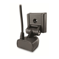
Overhead Mount
NOTE: Overhead and/or thin panels may require additional hardware (separate purchase required)
to securely mount the control head.
1. Place the bracket on the mounting surface aligned with the drilled holes. Fill one hole with
marine-grade silicone sealant.
2. Place one flat washer on a #10 x 1" wood screw and install the screw into the hole (see the
illustration Installing the Gimbal Bracket). Repeat for the remaining three holes.
3. Tighten each screw until it is secure.
4. Place the control head back onto the gimbal bracket (see Plan the Mounting Location for
details). Adjust the control head viewing angle as needed and tighten the gimbal knobs until
the assembly is secured. Hand-tighten only!
3
|
Connect Power
It is important to review the following information before you start the power installation:
Δ Cable Length: A 6' (2 m) long power cable is included. You may shorten or lengthen the cable
using 16 gauge multi-stranded copper wire. See the Recommended Power Cable Extension
Information table for details.
Recommended Power Cable Extension Information
Extension Length Wire Gauge
1 to 6 ft 18 AWG
6 to 12 ft 14 AWG
12 to 24 ft 12 AWG
Please consult a U.S. Coast Guard ABYC-approved wire gauge diagram or
a certified NMEA Marine Electronics Installer.
Δ Power Supply: The control head must be connected to a 12 VDC power supply using the fuse
size shown in the Required Fuse Size table.
Required Fuse Size
Model Fuse Size Fuse Type
APEX 13 5A slow-blow or MDL equivalent
APEX 16 7.5A slow-blow or MDL equivalent
APEX 19 7.5A slow-blow or MDL equivalent
Δ Fuse Panel or Battery: The control head power cable can be connected to the electrical system
of the boat at the fuse panel (usually located near the console), or directly to the battery. In
order to minimize the potential for interference with other marine electronics, a separate power
source (such as a second battery) may be necessary.
WARNING! Some boats have 24 or 36 Volt electric systems, but the control head MUST be connected
to a 12 VDC power supply.
WARNING! Make sure that the power cable is disconnected from the control head at the beginning
of this procedure.
WARNING! Humminbird® is not responsible for over-voltage or over-current failures. The control
head must have adequate protection through the proper selection and installation of the fuse size
shown in the Required Fuse Size table.

 Loading...