Do you have a question about the Hunter Crescent Falls and is the answer not in the manual?
Verify minimum clearance from blades to walls and floor.
Ensure outlet box is secured to structure and rated for fan support.
Check ceiling angle for standard or angled mounting compatibility.
Information on downrod length and angled mounting kits for angled ceilings.
Secure bracket using machine screws and washers to the outlet box.
Secure bracket using wood screws and washers to support structure.
Follow steps to attach adapter cover, remove setscrew, route wires, and secure downrod.
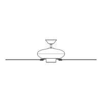
Slide canopy over downrod and wires, place downrod ball into ceiling bracket slot.
Lift fan housing or downrod to prevent damage; place downrod ball in bracket slot.
Connect fan wires to ceiling wires using wire nuts, ensuring proper grounding.
Ensure the ceiling fan is properly grounded; stop if ground wire is absent.
Fit canopy, align screw holes, insert canopy screws, and rotate if needed.
Rotate canopy 180 degrees if holes don't align; match hanger ball shape.
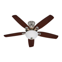
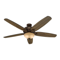
Secure each blade to the blade ring using blade nuts, screws, and washers.
Install light kit screws, feed wires, connect electrical components, and secure light kit.
Ensure all screws are tight to secure the light fixture to prevent falls.
Align and attach the glass globe to the light kit, ensuring proper engagement.
Install battery, pair remote, and set light kit toggle switch for correct bulb type.
Details on fan speed selection, reverse function, and light control (on/off/dimming).
Mount the transmitter cradle to the wall using provided screws.
Check power, motor switch, blade spin, and wiring connections if fan is not working.
Address wobbling by checking blade installation, hanger ball seating, and balancing.
Troubleshoot erratic remote function by checking battery and pairing, or multiple remotes.
Information on Hunter Fan Company's warranty coverage for motor and other parts.
Follow steps 1-5 to disassemble and remove the standard downrod pipe.
Follow steps 6-10 to reassemble the downrod assembly with a new pipe.
Ensure downrod is assembled correctly, pull on hanger ball, and reinsert pin.
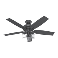
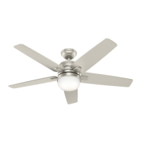
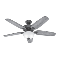
| Fan Type | Ceiling Fan |
|---|---|
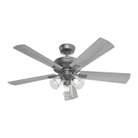
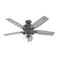
| Blade Span | 52 inches |
| Number of Blades | 5 |
| Indoor/Outdoor | Indoor |
| Light Kit Included | Yes |
| Number of Speeds | 3 |
| Motor Type | AC |
| Bulb Type | LED |