5
Wire Size Max Length
Gauge Feet
20 240
18 1,000
PLANNING
Planning is an important step in the successful installation of your Hunter ow meter and
the reliable operation of your irrigation system.
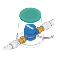
3. Flow meter entry location: Flow meters are installed between the master valve and zone valves. To avoid
false alerts, there should be no water taps or other uncontrolled water use on the downstream side of the
ow meter. If all solenoids connected to the controller are not grouped together, it may be necessary to install
more than one ow meter. The ow meter should be installed with 10 times the pipe diameter before and ve
times the pipe diameter aer the ow meter of straight pipe.
4. Cable: Two-wire cable is required. The cable gauge is determined by the total length of cable between the
controller and the ow meter. For cable lengths greater than 100′, lightning-prone areas, or cable running
near buildings, use shielded cable. The cable should consist of two dedicated wires and must not be in the
same conduit or cable bunch as the solenoid wires. Do not share the common wire of the solenoids with the
common of the sensors.
Flow Meter Cable Length Chart