TTENZIONE:
Nel
caso
le
tar
ghette
di
pericolo
risultino
illeggibili
o
siano state rimosse, sostituirle immediatamente.
Non
utilizzar
e
lo
smontagomme
se
mancante
di
una
o più tar
ghette di pericolo.
Non interporr
e oggetti che ne
ostruiscano la visione all'operator
e.
Per eventuali richieste utilizzar
e il
codice indicato nella pr
esente
tavola.
w
ARNING:
U
n
r
e
adab
l
e
a
n
d
m
i
ss
in
g
w
a
r
nin
g
l
ab
e
l
s
m
u
s
t
b
e
r
eplaced immediately.
Do
not
use
the
tIr
e
changer
if
one
or
mor
e
labels
ar
e missing.
Do not add any object that could
prevent the operator fr
om seeing the
labels.
Use the code in this table to or
der
labels you need.
9
CONTROLLO CORRETTO
FUNZIONAMENTO
9
CORRECT OPERA
TION
CHECKS
D
o
p
o
a
v
e
e
ff
e
tt
u
a
t
o
i
c
o
ll
e
g
a
m
e
n
t
i ri
c
h
i
e
s
t
i
(v
e
d
i
c
a
p
i
t
o
l
o
"
I
N
S
T
A
LL
A
Z
I
O
N
E
"
)
c
o
n
t
r
o
ll
a
r
e
il
c
o
rr
e
tt
o
f
un
z
i
o
n
a
m
e
n
t
o
d
e
ll
o
smontagomme ef
fettuando le seguenti operazioni:
Once
the
connections described
above
have
been
made
(
S
ee
“
I
n
s
ta
ll
at
i
o
n
”
)
,
c
h
e
c
k
t
o
m
a
k
e
s
u
r
e
t
h
e
tI
r
e
c
h
a
n
g
e
r
w
o
r
k
s
properly by carrying out the following pr
ocedur
es:
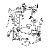
1)
Pr
emer
e
il
pedale
(
1,
Fig.
A)
verso
il
basso:
l'autocentrante
(
2,
F
i
g
.
A)
d
e
v
e
r
u
o
t
a
r
e
i
n
s
e
n
s
o
o
r
a
ri
o
(
p
e
r
TCX525
D
,
d
o
t
a
t
o
d
i
m
o
t
o
r
e
a
2
velocità:
-
premer
e
il
pedale
(
1,
Fig.
A)
verso
il
basso
in
po
-
sizione
inter
media;
l'autocentrante
deve
ruotar
e
in
senso
orario
a
ll
a
p
ri
m
a
v
e
l
o
c
i
t
à
;
-
p
r
e
m
e
r
e
il
p
e
da
l
e
a
f
o
n
d
o
;
l
'
a
u
t
o
c
e
n
t
r
a
n
t
e
deve ruotar
e in senso orario a doppia
velocità).
Spinger
e
il
pedale
(
1,
Fig.
A)
verso
l'alto:
l'autocentrante
(
2,
Fig.
A)
deve ruotar
e in senso antiorario.
N
.
B
.:
N
e
l
c
a
s
o
il
s
e
n
s
o
d
i
rot
a
z
i
o
n
e
r
i
s
ulti
o
pp
o
s
t
o
a
q
u
e
ll
o
p
r
e
c
e
d
e
nt
e
m
e
nt
e
d
e
s
c
r
itt
o
,
è
n
e
c
e
ss
a
r
i
o
f
a
r
e
in
v
e
r
ti
r
e
(
da
personale
pr
ofessionalmente
qualifi
cato)
tra
lor
o
due
cavi
di
fase sulla spina trifase.
2)
Aprir
e
manualmente
il
braccio
stallonator
e
(
4,
Fig.
A)
e
pr
e
-
mer
e
il
pedale
stallonator
e
(
3,
Fig.
A)
:
lo
stallonator
e
entra
in
funzione richiudendosi.
3)
Pr
emer
e
a
fondo
il
pedale
(
5,
Fig.
A
):
le
quattr
o
grif
fe
di
bloc
-
caggio
(
6,
Fig.
A)
dell'autocentrante
devono
aprirsi.
Pr
emendo
nuovamente il pedale le quattr
o grif
fe devono chiudersi.
4
)
P
r
e
m
e
r
e
il
p
e
da
l
e
(
7,
F
i
g
.
A)
p
e
r
c
o
n
s
e
n
t
ir
e
il
ri
b
a
l
t
a
m
e
n
t
o
d
e
l
palo (
8, Fig. A
) all'indietr
o in posizione di "fuori lavor
o".
Pr
emendo
nuovamente
il
pedale:
il
palo
ritor
nerà
in
posizione
di lavoro.
5)
Pr
emer
e il pulsante giallo (
pos. A, fig. C
) della maniglia (
9,
1)
Depr
ess
pedal
(
1,
Fig.
A)
down:
the
table
top
(
2,
Fig.
A)
should
tur
n
clockwise
(
for
TCX525
D
with
a
2-speed
motor:
pr
ess
p
e
da
l
(
1,
F
i
g
.
A)
d
ow
n
t
o
i
t
s
m
i
dd
l
e
p
o
s
i
t
i
on
a
n
d
t
h
e
tab
l
e
top
should
tur
n
clockwise
at
the
low
speed.
Push
the
pedal
all
the way
down
and
the table
top should
tur
n
clockwise
at
high speed).
Pull
the
pedal
(
1,
Fig.
A)
up
and
the
table
top
(
2,
Fig.
A)
should
tur
n anticlockwise.
NB:
if
the
tur
ning
dir
ection
is
the
opposite
of
what
is
described
her
e,
switch
two
wir
es
in
the
thr
ee-wir
e
plug
(this
should
be
down by a qualifi
ed electrician).
2)
Open
the
bead
loosener
ar
m
(
4,
Fig.
A)
manually
and
de
-
pr
ess
the
bead
loosener
pedal
(
3,
Fig.
A
):
the
bead
loosene
will close.
3)
Depr
ess
the
pedal
all
the
way
down
(
5,
Fig.
A
):
the
four
clamps
(
6,
Fig.
A)
on
the
table
top
will
open.
When
the
pedal
is depr
essed again, the clamps should close.
4)
Depr
ess
the
pedal
(
7,
Fig.
A)
to
tilt
the
post
(
8,
Fig.
A)
back
to non-working position.
Depr
ess
the
pedal
again,
the
post
will
r
ecouple
in
its
working
position.
5)
Pr
ess
the
yellow
button
(
Pos.
A,
Fig.
C
)
on
the
handle
(
9,
Fig.
A
): vertical slide (
10, Fig. A
) and swing arm (
11, Fig. A
) will be
22