English – 3
EN
5.1 - Programming warnings
• In general
-Strictlyobservethetimelimitsspeciedintheprocedures.
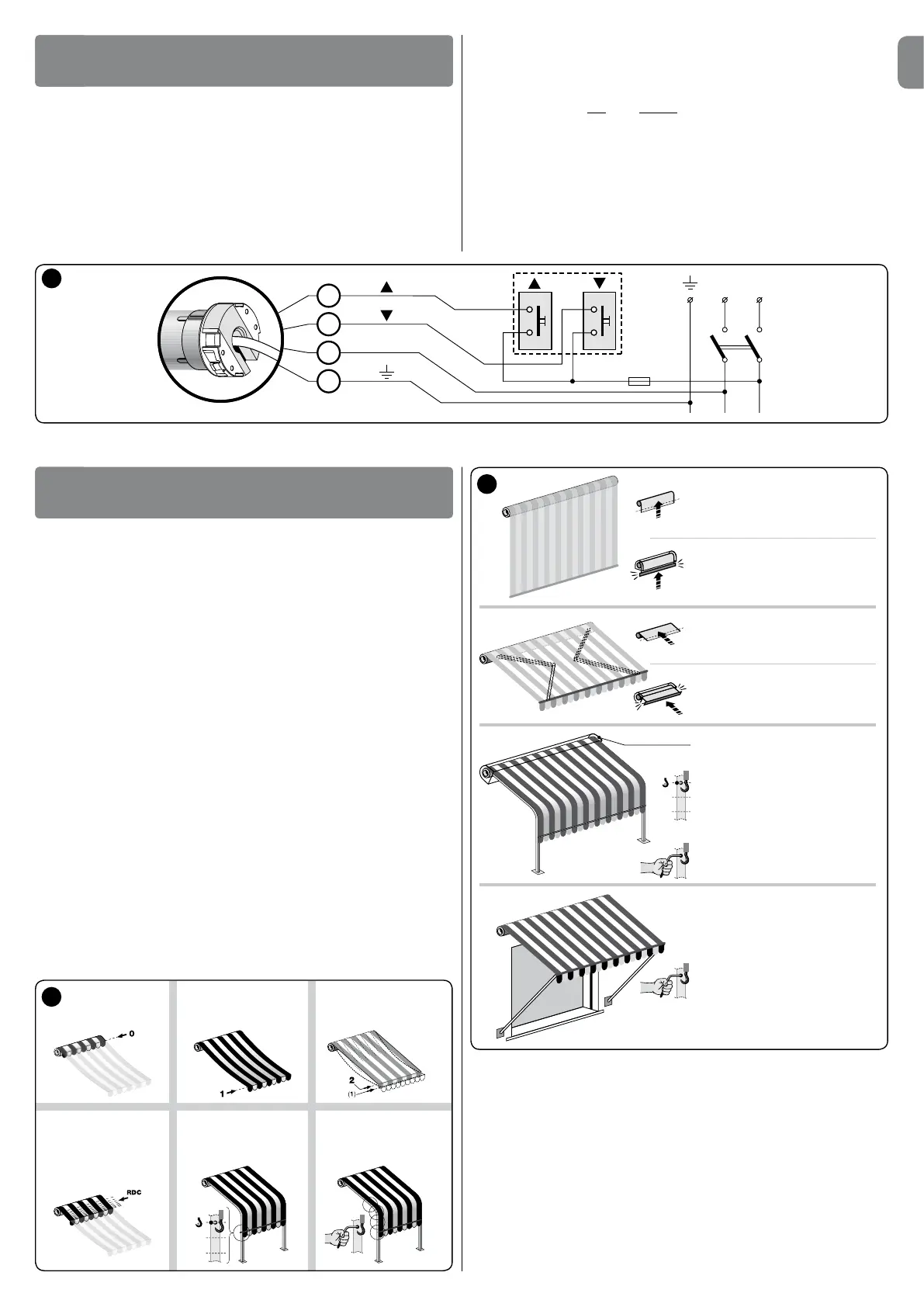
- Positions 0, 1, 2, and Softheawning,speciedinthetext,correspondtothose
illustrated in g. 5.
• Motor signals
o The motor implements one very short interruption at the start of the ma-
noeuvre and then resumes movement = only 1 limit switch is memorised.
o The motor implements two very short interruptions at the start of the
manoeuvre and then resumes movement = no limit switch is memorised.
o when the control button is pressed (“hold-to-run” mode), movement is
started but is interrupted shortly afterwards, without completing the ma-
noeuvre = proceed with total deletion followed by programming of the limit posi-
tions.
5.2 - Limit switch programming
Limit switches “0” and “1” (g. 5) correspond to the positions of the awning at the
endoftheUpmovements(“0”)andtheendoftheDownmovements(“1”).
To select the procedure most suited to the system features, refer to g. 6.
• Note on “RDC” function
The RDCfunctionpreventsthecanvasfromremainingexcessivelytensionedatthe
end of the closing ma noeuvre. The function automatically reduces the motor traction
torqueduringthenalphaseoftheclosingmanoeuvre(tosettherequiredtorque
value, refer to paragraph 5.5).
This function is set at the factory, however it is not applicable if the limit switches are
programmedusingthemanualmode(paragraph5.3).Itcanbedisabledonlydur-
ing the programming of the limit switches in semi-automatic mode (paragraph 5.4).
6
Manual procedure
paragraph 5.3
Semi-automatic procedure
paragraph 5.4
Manual procedure
paragraph 5.3
Semi-automatic procedure
paragraph 5.4
Semi-automatic procedure
paragraph 5.4
“FTC”
option (paragraph 5.7)
“FTA” option (paragraph 5.8)
Manual procedure
paragraph 5.3
“FTA” option (paragraph 5.8)
5
position “0” position “1”
Force reduction on
closure (function
“RDC”)
position “2”
Fabric tensioning
(function “FRT”)
position “S”
Automatic hook-up
(function “FTC”)
Manual hook-up
(function “FTA”)
Caution!
-Incorrectconnectionscancausefaultsorhazardoussituations.
-Strictlyobservetheconnectionsspeciedinthismanual.
- A disconnect device must be installed on the product power supply line, with a gap
betweencontactstoensurecompletedisconnectioninovervoltagecategoryIII,in
compliance with installation regulations (the disconnect device is not supplied with
the product).
For electrical connections, refer to the wiring diagram in g. 4. More than one
motor can be controlled with one single pushbutton control panel by connecting
the motors “in parallel”The cable for electrical connections of the tubular motor has
4 internal wires:
ELECTRICAL CONNECTIONS
4
PROGRAMMING
5
Brown
Black
Blue
Yellow-green
– Brown: = electric ascent/descent phase.
– Black: = electric descent/ascent phase.
– Blue: = Common (usually connected to Neutral).
– Yellow-green: = Earth (equipotential bonding connection).
• Associating the Up and Down movements with the respective
pushbuttons
After making the connections, run a number of manoeuvres (*) to ensure that the
ascent and descent movements are associated correctly with the respective control
buttons.Ifthisisnotso,inverttheconnectionoftheBrown and Black wires.
(*)–Duringexecutionofthemanoeuvre,ensurethattheawningcompletes2short
movements (= operator connected correctly). The direction of motor rotation is not
important.
4
 Loading...