FUEL SYSTEM
G
10
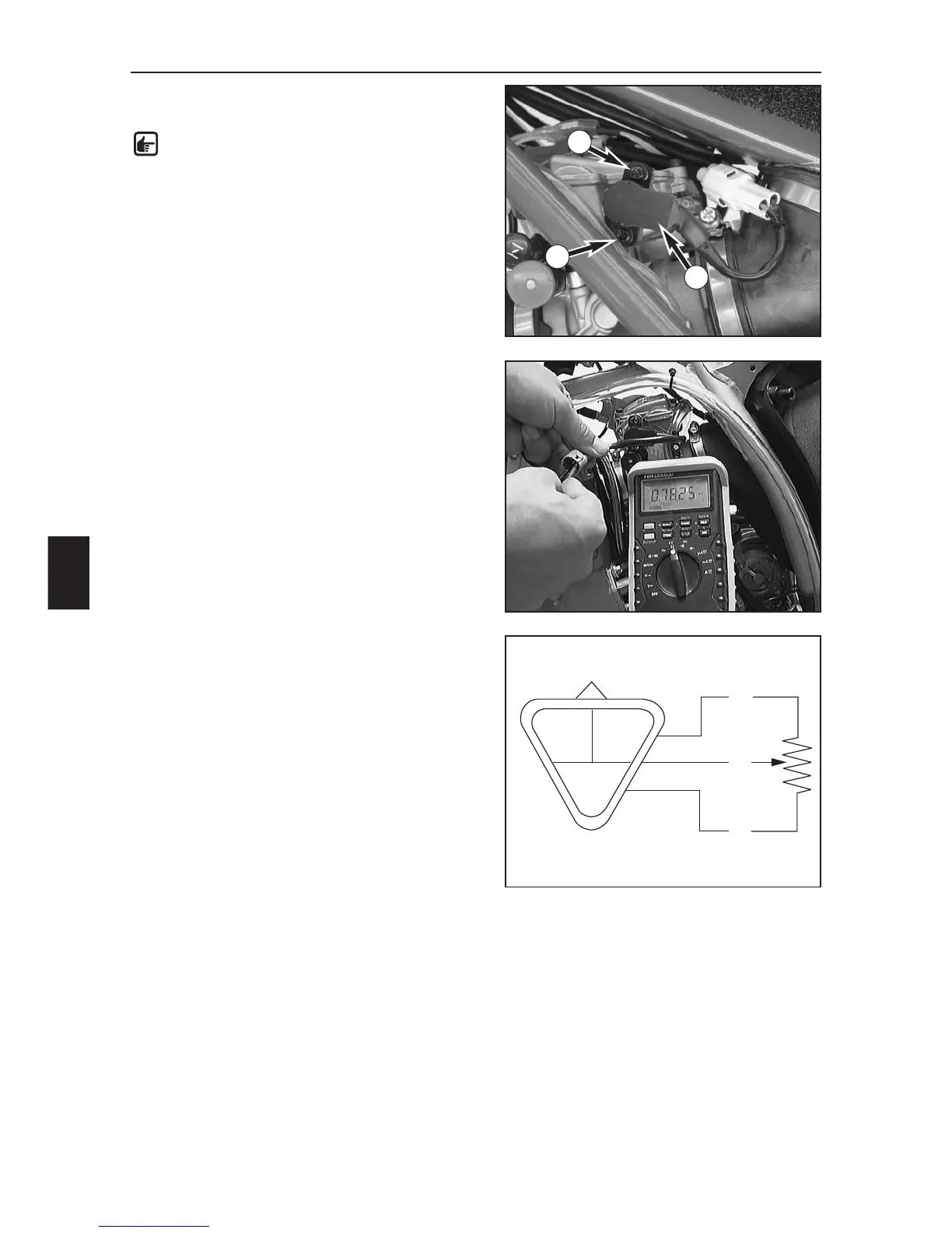
ADJUSTING THE POSITION OF THE
THROTTLE SENSOR
NOTE: The idle speed must be correctly
adjusted before you check the position of the
throttle sensor.
–Disconnect the plug and socket connection on the
throttle sensor.
– Connect a multimeter (measuring range Ω x 1k) to the
blue (+) and the black (–) cable on the throttle sensor
and measure the throttle resistance.
– Multiply this value by 0.15 to obtain the setting for the
throttle sensor.
Example:
Throttle sensor resistance (bl/b) = 5 kΩ
Throttle sensor resistance (y/b) = 5 kΩ x 0,15 =
750 Ω ± 50 Ω
– Connect the multimeter (measuring range Ω x 100) to
the yellow (+) and the black (–) cable on the throttle
sensor and measure the throttle sensor resistance with
the throttle grip closed.
According to the above example, this value should be
750 Ω ± 50 .
– If the measured value does not correspond to the
setpoint value, loosen the 2 screws (1) and turn the
throttle sensor (2) until the measuring device displays
the setpoint value.
–Fix the throttle sensor in this position by tightening the
screws and check the value again.
– Connect the throttle sensor to the cable tree.
1
1
2
bu
bu
ye
ye
bl
bl
bu = blue
ye = yellow
bl = black
 Loading...