19
• Turn steering wheel to position wheels straight for-
ward.
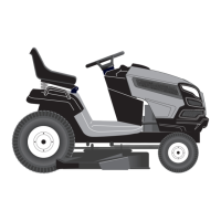
• ATTACH FRONT LINK (E) - Work from left side of trac-
tor. Insert rod end of link assembly through front hole
in tractor front suspension bracket (F) and secure with
retainer spring (G) through hole in link located behind
the bracket.
• Insert other end of link (E) into hole in front mower bracket
(H) and secure with washer and retainer spring (J).
A
B
C
D
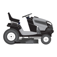
• ATTACH REAR LIFT LINKS (C) - Lift rear corner of
mower and position slot in link assembly over pin on
rear mower bracket (D) and secure with washer and
retainer spring.
• Repeat on opposite side of tractor.
FIG. 20
FIG. 21
E
F
H
G
J
FIG. 22
SERVICE AND ADJUSTMENTS
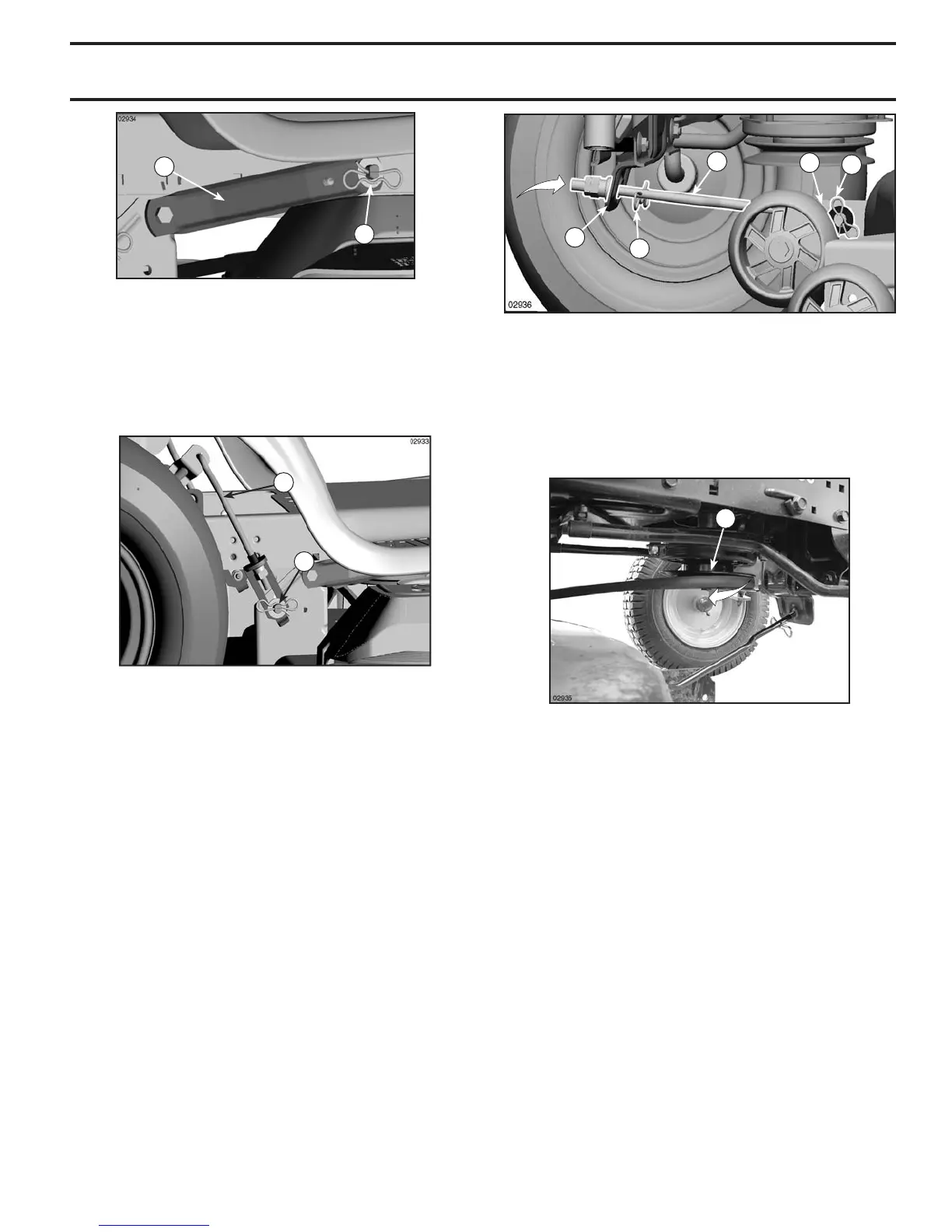
M
FIG. 23
• Disengage belt tension rod (K) from locking bracket
(L).
• Install belt onto engine clutch pulley (M).
IMPORTANT: Check belt for proper routing in all mower
pulley grooves.

 Loading...