778845 Rev. 7/04
3-1
OPERATION
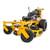
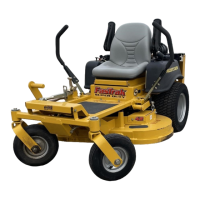
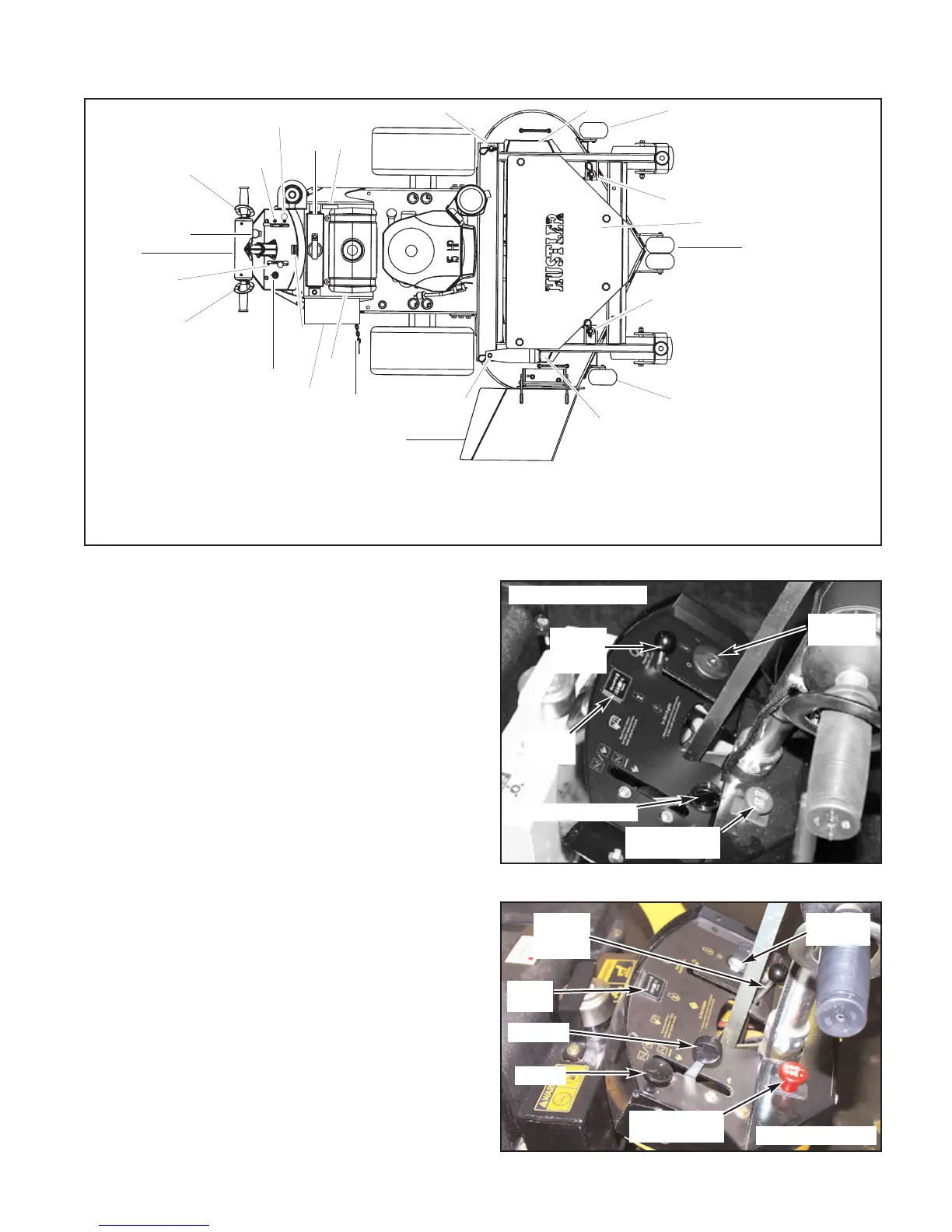
Figure 3-1
Controls
For general location of the controls described in this
section, refer to Figure 3-1.
1. Ignition switch (Fig. 3-2) – (Recoil start) a two
position switch: off and run. With key inserted, rotate
it clockwise to RUN position.
(Electric start) a three position switch: off, run, and
start. With key inserted, rotate it clockwise to START
position; release key when engine starts, and switch
will automatically return to the RUN position.
2. Throttle/Choke (Fig. 3-2a) — a cable is linked to
engine throttle for controlling engine speed. Move
lever forward to increase engine rpm, move lever
rearward to decrease engine rpm.
To reach the choke position, push forward on the lever
as far as it will go. As the lever is pushed forward you
will notice a detente position, when the lever is moved
past this point, the choke is engaged.
Throttle (Fig. 3-2b) — a cable is linked to engine
throttle for controlling engine speed. Move lever
forward to increase engine rpm, move lever rearward
to decrease engine rpm.
Choke control (Fig. 3-2b) – a cable is linked to
manually operate the engine choke. When the knob is
in the down position, the choke is in the off (run)
position. When the knob is pulled up, the choke is in
the on (start) position. Do not operate the machine in
the on (start) position.
3. H-bar handle (Fig. 3-3) — this handle controls the
unit’s acceleration, speed, steering direction and
dynamic braking.
1. Ignition Switch 5. H-bar handle 10. Height adjusting pins 15. Left deck cover
2a. Throttle/Choke Lever 6. Deck clutch switch 11. Hydraulic reservoir 16. Center deck cover
2b. Throttle 7. Operator presence control lever 12. Discharge chute 17. Right deck cover
3. Serial number plate 8. Anti-scalp wheels 13. Pump clutch chain 18. Battery (electric start only)
4. Neutral Lock Lever 9. Hour meter 14. Fuel tank 19. Choke knob
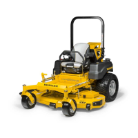
WalkBehind
Controls
11
1
6
2a
2b
4
5
14
13
9
8
3
8
8
12
10
10
10
10
7
7
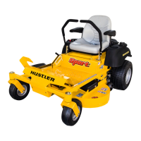
Ignition
switch
Throttle/Choke
Neutral
lock
lever
Deck clutch
lever
Hour
meter
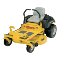
Figure 3-2a
15
16
17
18
19
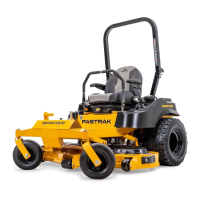
Figure 3-2b
Ignition
switch
Throttle
Neutral
lock
lever
Deck clutch
lever
Hour
meter
Choke
23/25
HP shown
15/17/19 HP shown
 Loading...