606653 3-1 REV A
OPERATION
Safe Operating Practices
Refer to the Safety Precautions section of this manual for
operational and personal safety information.
Instrument Panel
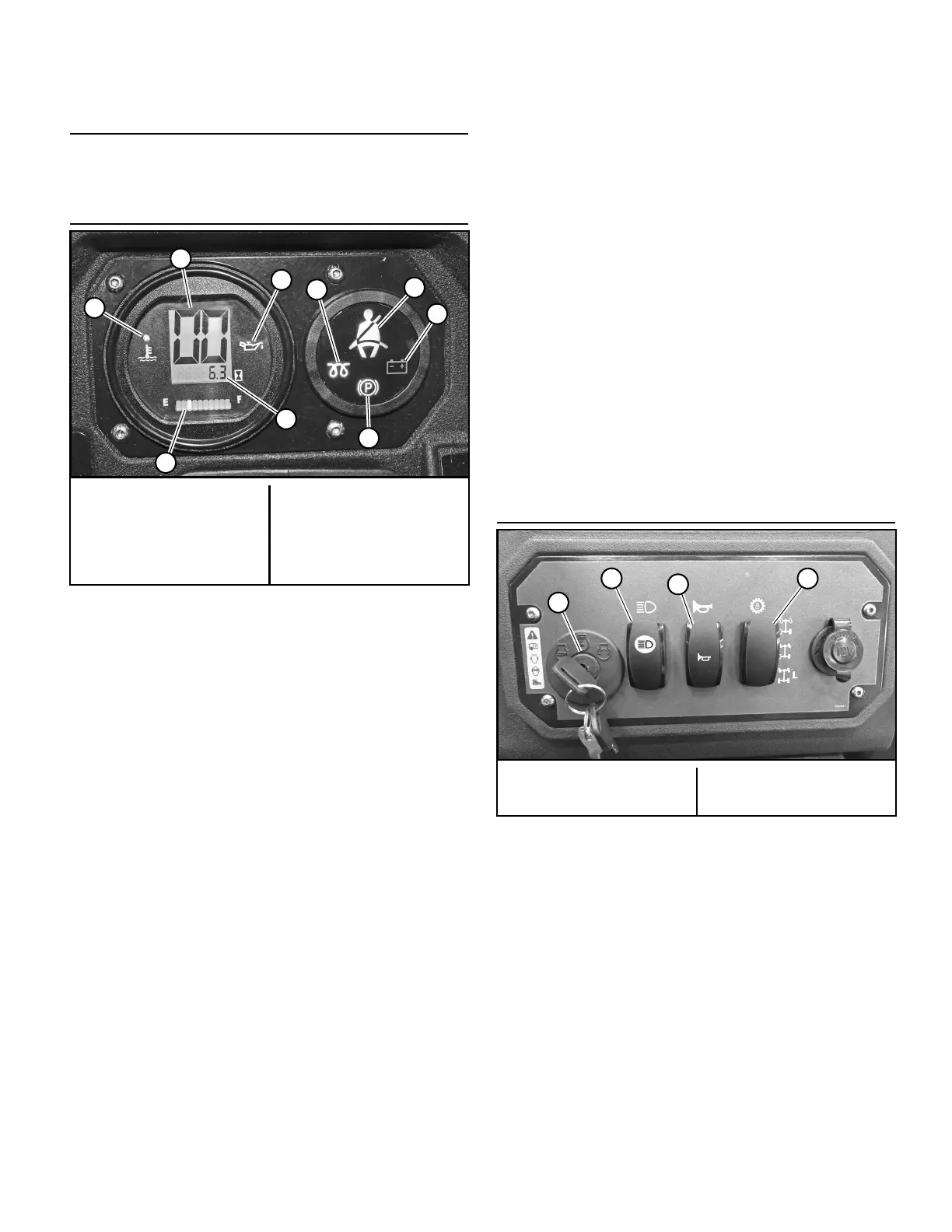
A. Coolant light (Figure 3-1) — this light will come on when
the engine coolant temperature exceeds intended level
during operation. If light comes on, shut down the
machine as soon as reasonable. Never risk continued
operation when light remains on; high temperatures
can severely damage the engine.
B. Speedometer (Figure 3-1) — indicates the ground speed
the vehicle is traveling.
C. Oil light (Figure 3-1) — this light comes on when the
ignition switch is placed in the “PREHEAT/RUN” posi-
tion and stays lit until the engine is running and a
specified oil pressure is developed. If the light comes
on during operation, shut the engine off immediately
and locate and correct the problem.
D. Glo–plug light (Figure 3-1) — this light comes on when
the ignition switch is turned to the “PREHEAT/RUN”
position and held. It shows that power is going to the
glo-plugs. Wait for the light to go off before starting
the engine.
E. Seat belt light (Figure 3-1) — this light comes on when
the ignition switch key is initially turned to “PRE-
HEAT/RUN” position. It will remain for 30 seconds to
remind the operator and passenger to use the seat
belts for personal protection.
F. Alternator light (Figure 3-1) — this light comes on when
the ignition switch is placed in the “PREHEAT/RUN”
position and stays lit until the engine is running and
the voltage exceeds the minimum operation require-
ments.
If light comes on during operation, shut the engine off,
locate and correct the problem. If light remains on
while the engine is running, it indicates that the
battery is being discharged.
G. Park brake light (Figure 3-1) — this light comes on when
the ignition switch key is turned to the “PRE-
HEAT/RUN” position and the park brake lever is in the
engaged position. It will remain lit until the park brake
lever is moved to the disengaged position.
H. Hour meter (Figure 3-1) — registers in 1/10 hour incre-
ments. It is connected to the ignition switch. It records
the accumulative time while the ignition key is
switched to the “PREHEAT/RUN” position.
I. Fuel gauge (Figure 3-1) — indicates the amount of fuel
in the fuel tank when the ignition switch key is in the
“PREHEAT/RUN” position.
Controls
A. Ignition switch (Figure 3-2) — a three position switch:
“OFF”, “PREHEAT/RUN”, and “START”. With the key
inserted, rotate it clockwise to the “PREHEAT/RUN”
position. After pre-heat has occurred and glo-plug light
goes off, depress the brake pedal, rotate the key to the
“START” position; release the key when the engine
starts, and the switch will automatically return to the
“RUN” position. Do not hold in the “START” position
more than 10 seconds.
B. Head light switch (Figure 3-2) — turns the vehicle’s
headlights on and off when the ignition switch key is in
the “RUN” position.
C. Horn switch (Figure 3-2) — activates the vehicle’s horn
when the ignition switch key is in the “RUN” position
and the switch is depressed.
A. Coolant light
B. Speedometer
C. Oil light
D. Glo–plug light
E. Seat belt light
F. Alternator light
G. Park brake light
H. Hour meter
I. Fuel gauge
Figure 3-1
A. Ignition switch
B. Head light switch
C. Horn switch
D. Traction control switch
Figure 3-2