111251CE_1109 3-3
V Never carry children, even with the blades off. They may
fall off and be seriously injured or interfere with safe
machine operation.
V Never allow children to operate the machine.
V Use care when approaching blind corners, shrubs, trees,
the end of a fence or other objects that may obscure
vision.
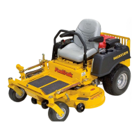
Controls
A. Ignition switch (Fig. 3-1) — (Recoil start) a two
position switch: off and run. With key inserted, rotate it
clockwise to RUN position.
B. Throttle control (Fig. 3-1) — a cable is linked to engine
throttle for controlling engine speed. Move lever forward
to increase engine rpm, move lever rearward to decrease
engine rpm.
C. Choke control (Fig. 3-1) — a cable is linked to manually
operate the engine choke. When the knob is in the down
position, the choke is in the off (run) position. When the
knob is pulled up, the choke is in the on (start) position.
Do not operate the machine in the on (start) position.
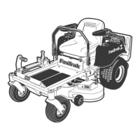
D. H-Bar handle (Fig. 3-2) — this handle controls the
unit’s acceleration, speed, steering direction and dynamic
braking.
E. Deck clutch switch (Fig. 3-1) — this switch engages the
deck. Pull the switch up to engage and push switch down
to disengage the clutch.
IMPORTANT: Never engage clutch with engine run-
ning at high rpm or when the deck is under load. Clutch,
belts or deck could be damaged.
F. Neutral lock/park brake lever (Fig. 3-1) — when this
lever is in the neutral lock/park brake position, the
transaxles are in neutral and the unit will not move.
Moving the lever out of the neutral lock/park brake
position and forward engages the transaxles and allows
the H-bar handle to be rotated.
G. Operator presence control levers (Fig. 3-2) — engages
the operator presence switches. If the switch is not
engaged the unit will not operate. Refer to the Safety
Interlock system for more information.
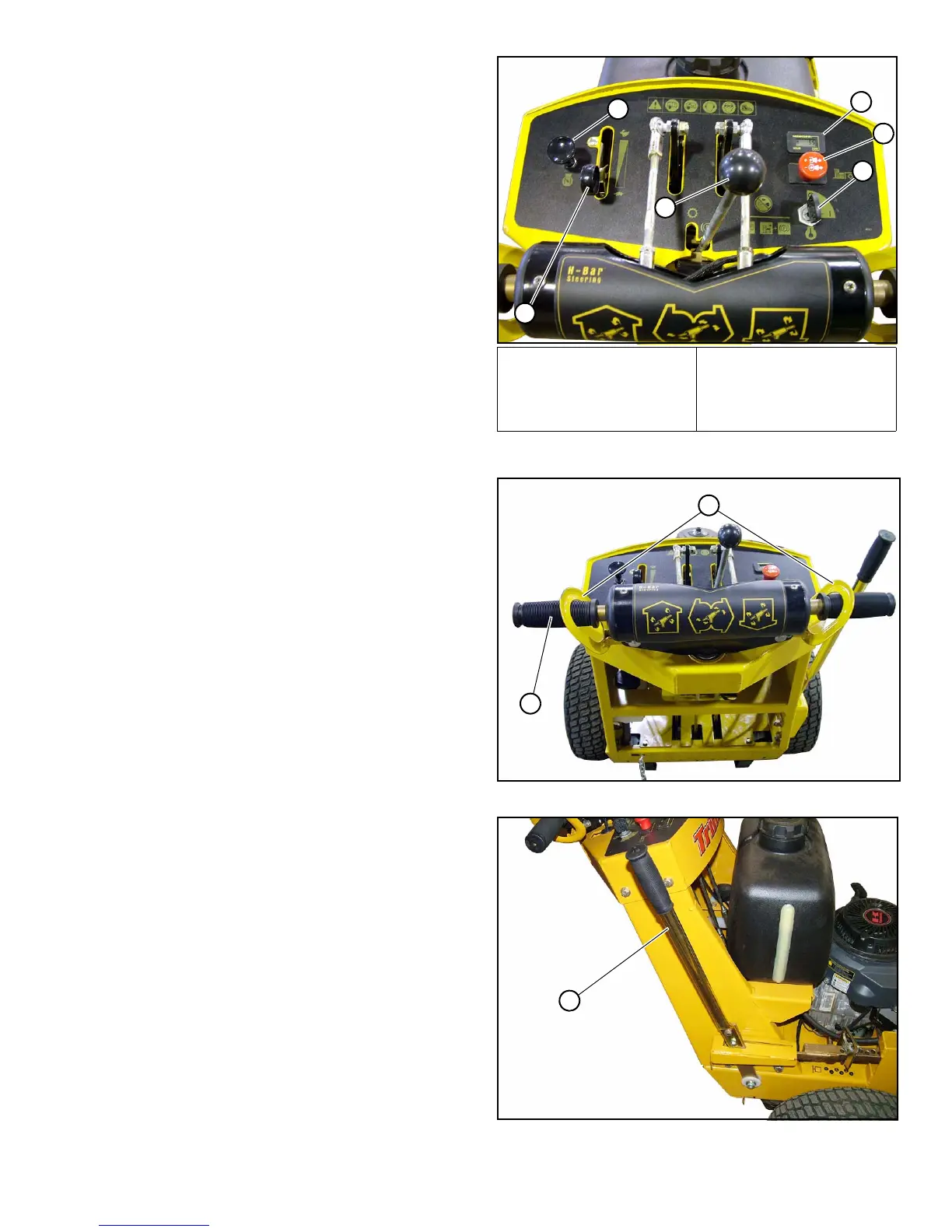
H. Deck lift lever (Fig. 3-3) — the deck lift lever is used to
raise or lower the deck. Pull rearward on the lever to raise
the deck and then place the deck height locking pin into
the desired cutting height hole.
Pull the deck lift lever to raise the deck when going over
obstructions.
Instrumentation
I. Electronic hour meter (Fig. 3-1) — registers 1/10 hour
increments up to 9,999.9 total hours. Connected to the
ignition switch, the meter records the accumulative time
while the ignition key is switched to the RUN position.
Safety start interlock system
The unit is equipped with a safety interlock system consisting
of the neutral lock switch, operator presence control lever
switches and deck clutch switch. Fig. 3-2
Check the safety interlock system daily, prior to operation.
This system is an important safety feature. It should be repaired
immediately if it malfunctions. The machine incorporates two
A. Ignition switch
B. Throttle
C. Choke
E. Deck clutch switch
F. Neutral lock/park brake
lever
I. Hour meter
Fig. 3-1
Fig. 3-2
Fig. 3-3

 Loading...