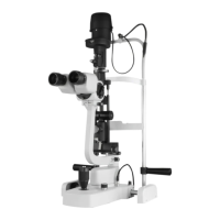
The Huvitz Slit Lamp Microscope is a sophisticated ophthalmic instrument designed for detailed examination of the eye. It facilitates stereomicroscopic examination of the eye under slit light and microscopic examination of the ocular fundus and posterior vitreous body, often utilizing a Hruby's lens. This device is intended for use by ophthalmologists and optometrists.
Device Structure and Components:
The slit lamp is broadly divided into three main modules: the Microscope Module, the Illumination System, and the Mechanical Body.
Illumination System (HS-5000, HS-7000):
The illumination system is crucial for providing the necessary light for examination.
- Light source: Halogen lamp (12V 30W) or LED.
- Slit length: Adjustable from 0.3 to 12mm.
- Slit width: Continuously adjustable from 0 to 12mm.
- Slit projection: 1x magnification.
- Aperture diaphragm: Multiple settings including 0.3, 1, 3, 5, 9, and 12mm.
- Filters: Includes cobalt blue, ND (gray), heat absorption (IR), and red-free (green) filters.
- Cobalt blue filter: Used with fluorescein dye for enhanced visualization.
- Green filter (red-free): Obscures red elements, making blood vessels or hemorrhages appear black.
- Neutral Density (ND) filter: Reduces the amount of light.
- Heat absorption (IR) filter: Absorbs heat from the light source, protecting the patient's eye.
- Slit rotation: Continuously adjustable from 0 to 180 degrees.
Illumination System (HS-5500, HS-7500):
This model includes additional features for enhanced illumination control.
- Light source: Halogen lamp (12V 30W) or LED.
- Slit length: Adjustable from 0.3 to 12mm.
- Slit width: Continuously adjustable from 0 to 12mm.
- Filters: Includes cobalt blue, ND (gray), heat absorption (IR), and red-free (green) filters.
- Slit rotation: Continuously adjustable from 0 to 180 degrees.
- Horizontal tilting: Allows for slit movement (left & right).
- Vertical tilting: Enables angle change for the slit.
- Diffuser: Used for diffusing the light, providing a broader, softer illumination.
Microscope:
The microscope module provides various magnification options and adjustments for optimal viewing.
- Type: Galilean converging binocular (8°).
- Eyepiece: Available in 12.5x and 10.0x.
- Diopter adjustment: ±5D.
- PD adjustment: Adjustable from 55 to 80mm.
- Filter: Includes a yellow filter.
- Yellow filter: Fits RGP lenses with fluorescein dye. It's important to check if the yellow filter is removed after installation if not needed.
- Magnification: 5 positions rotating drum.
- Total magnification & real field of view:
- 6x (38.5mm)
- 10x (22.2mm)
- 16x (15.2mm)
- 25x (10.5mm)
- 40x (6.7mm)
Part Names (Key Components):
The device features numerous components for precise control and patient comfort:
- Fixation point
- Control lever for changing enlargement
- Removable eye-pieces
- Knob for clamping the breath screen
- Breath screen
- Control handle for the slit rotation 90-0-90
- Connecting plug of the projector lamp
- Knurled ring for filters insertion
- Movements (x y z)
- Base with orthogonal movements
- Shaped tabletop
- Warning light of the SMPS
- Main switch
- Luminosity selector
- SMPS box
- Drawer
- Toothed guides
- Wheel protection Cases
- Sliding plate
- Knob to lock the projector
- Scale for the projector position
- Locking pins for chin rest paper
- Chin rest
- Knobs to change the slit width
- Pointer for the eye positioning
- Head rest
- Microscope
- Knob to lock the base of the instrument
- Knob to lock the microscope
- Control handle for horizontal tilting
- Control lever for vertical tilting
- Microscope position stop
- 90-0-90 determining the inclination of the slit during rotation
- Lamp cover
- Microscope arm
- An optical group of the slit projector
- Patient's handle
- Chin rest fastening screw
- Wheel
- Mirror
- Capture connector (For the image system)
- Capture switch
- Luminosity selector connector (Connecting to the SMPS)
- Head rest module
- LED Lamp (Option)
Installation and Setup:
Table Installation:
The slit lamp can be installed on a TABLE MODULE (HS-5000) or a CIT-5000 (Made by HUVITZ) or a country-specific model.
HS-5000/7000 Installation:
- Table Ass'y, Main Body Ass'y, Microscope Ass'y, Illumination Ass'y, Head rest module: These main assemblies are installed.
- Rotation Guide Bolt, Screw M3, Bolt M6, Stopper shaft: These components are used for securing and guiding parts.
- Microscope Assembly: Ensure the microscope is assembled until it reaches the end of the stopper. Use a test bar to check if the focus is aligned. Move the entire microscope until the figure (sight) becomes clear.
- Cable Connection: Connect the connector to the cable carefully.
HIS-5000/5000U Camera Installation (HS-5000/7000):
- Remove cover and old camera cables: Loosen screws to remove the cover and disconnect existing camera cables.
- Drill hole (HS-7000/7500 only): Drill a 9mm hole and connect the USB camera connector, ensuring proper contact with the bump.
- Assemble camera board: Connect the 4-pin USB cable to COM3 and the 2-pin cable to COM4. Ensure cables are not twisted.
- Assemble cover and light sensor plate: Attach the cover and the light sensor plate to the table.
- Auxiliary light module separation (Halogen/LED):
- For Halogen: Loosen side screws to separate the cover.
- For LED: Use a 2.5mm hexagonal wrench for separation.
- Separate the basic cover.
- Mount auxiliary light illumination module: Install the LED and PCB.
- Tighten screw and insert cover: Tighten the screw on the upper side and turn to insert the cover.
- Assembly with support fixture: Assemble the auxiliary illumination module with its support fixture.
- Assemble scatter: Attach the scatter.
- Separate microscope binocular: Disconnect the binocular.
- Attach camera ass'y and reassemble microscope: After attaching the camera assembly, reassemble the microscope.
- Connect camera communication and USB cable: Connect these cables to the camera assembly.
- Connect camera communication cable in base: Connect the cable in the base.
- Fix cables: Secure cables in the holder to prevent interference during operation.
- Turn on and operate.
HS-5500/7500 Installation:
The installation steps are largely similar to the HS-5000/7000, with specific differences in the auxiliary light module and cable connections.
- Remove cover and old camera cables.
- Drill hole (HS-7000/7500 only): Drill a 9mm hole and connect the USB camera connector.
- Assemble camera board: Connect the 4-pin USB cable to COM3 and the 2-pin cable to COM4.
- Attach light sensor plate and combine scatter.
- Connect auxiliary illumination module and SMPS: Connect the auxiliary illumination module and its cable to the SMPS.
- Attach camera ass'y and reassemble microscope.
- Connect camera communication and USB cable.
- Connect camera communication cable in base and fix cables.
- Turn on and operate.
Focusing (Camera):
- Eyepiece focus: Adjust the eyepiece diopter to focus on the target.
- Digital camera focus (HIS-5000U CAMERA): Watch the camera video to focus. Loosen the lock with a 1.3mm hex wrench and use one-party drivers to focus.
- Digital camera focus (DSLR Adapter): Loosen three bolts with a 1.5mm hex wrench and turn the ring back and forth to focus. Use a coin to turn the ring left and right to switch the view.
LED Lamp Installation (HS-5000/7000):
- Separate existing halogen lamp cover: Loosen screws on the side.
- Separate halogen lamp module.
- Affix LED lamp module: Tighten with a 2.5mm hex wrench.
- Connect connector and light-fiber.
- Replace SMPS and drawer.
- Connect power and cable again.
LED Lamp Installation (HS-5500/7500):
- Disassemble screw cover and knob: Loosen screws to separate the cover.
- Separate fixed bracket of halogen lamp.
- Separate connector: Use a 2mm string or nipper to cut.
- Connect LED Connector.
- Assemble LED bracket: Tighten screws in the middle hole.
- Connect cable to cover.
- Replace SMPS and drawer.
NEW SMPS Installation (for reference):
The new SMPS features a setting switch.
- Halogen main light (HS-5000, HS-5500, HS-7000, HS-7500): Connect the main light connector to CON4 (HALOGEN). Adjust the switch as indicated in the manual (specific switch settings for each model).
- LED main light (5000/7000/5500/7500): Connect the main light connector to CON10 (MAIN_LED). Adjust the switch as indicated (specific switch settings for each model).
- LED main light + LED auxiliary light (5000/7000): Connect the main light connector to CON10 (MAIN_LED). Adjust the switch as indicated (specific switch settings for each model).
- Reducing 75% of halogen light (HS-6300): Connect the main light connector to CON10 (MAIN_LED). Adjust the switch as indicated (specific switch settings for HS-6300).
Joystick Driver Installation:
- Select COM port: Identify the COM port connected to the Joystick in Device Manager (Ports (COM & LPT)). Look for "Silicon Labs CP210x USB to UART Bridge" and set the COM number.
Option: Stand Alone Table Top:
Useful for setting up the unit table independently.
Allows measurement of distance, angle, dimension, and diameter through the shot. Refer to the S/W manual for more details.
Maintenance Features:
Repair - Halogen Projection Bulb:
- Disconnect power.
- Remove screws (24) and cover (39).
- Remove socket from bulb stems.
- Rotate knob (54) to loosen bulb stopper.
- Remove the old bulb: Be cautious as it may be hot.
- Replace with a new 12V30W Halogen bulb: Use the plastic envelope and avoid touching the bulb with fingers.
- Fasten the bulb with the knob.
- Warning: Do not touch the lamp house during operation as it heats up.
Repair - Fuse:
- Disconnect power.
- Remove the fuses housing.
- Replace the fuses.
Troubleshooting:
Not aligned focus between microscope and image:
- Adjust diopters after setting a slit-lamp target.
- Align camera focus using the 4.3F adjustment method.
- Modifying the target's angle to about 45 degrees can improve focus clarity.
- If problems persist, contact the agency.
Image is black out:
- Check cable connection between camera and computer.
- Verify proper camera driver installation.
- Check camera selection option in the program (refer to software manual).
It doesn't capture the image:
- Check proper joystick driver installation.
- Verify joystick serial port setup on the computer (refer to S/W manual).
- The joystick port is usually listed at the bottom of the software list.
The left and right movement was not realized:
- The PCB ASSY (Z1_USB_JOYSTICK) has a location correction function using a PI Sensor.
- Steps:
- Press the Joystick Button for 4 seconds.
- Move the Slit lamp from the far left to the far right.
- To exit the location correction function, click the Joystick Button again.
- Notice: This function can be executed if power is supplied to the PCB ASSY (Z1_USB_JOYSTICK) and is irrelevant to the HIS program.
Computer can't realize the camera (USB and DSLR type camera):
- This issue may occur with the latest iMac (2013) models with USB 3.0 ports.
- Solution: Connect the camera and Slit Lamp Body to the computer using separate USB cables instead of a Y-cable. If using a Y-cable for the Slit Lamp Body and a USB cable for the HIS Camera, an additional USB cable is needed for the latest iMac (2013) models with USB 3.0 ports.