EasyManua.ls Logo

Hy-Security 222 SS User Manual

Hy-Security 222 SS
78 pages
To Next Page IconTo Next Page
Page #1 background imageLoading...
Page #1 background image
Hy-Security
Gate Operators
HYDRAULIC
SLIDE GATE
Operators
With Smart Touch Controller
Installation and Maintenance Manual
Models 222 SS, E, EX, XI
333 MS, E, EX
222 CF, CE, CX
444 XS
and
DC Battery Operated Models
222 DS, DE, DX
444 DX
Revision: ___
Hy-Security Gate Operators
Phone: 1-800-321-9947
FAX: (206) 286-0614 INSTR# 103
Internet: www.hy-security.com
Email: Info@hy-security.com Date 04/01/02

Table of Contents

Question and Answer IconNeed help?

Do you have a question about the Hy-Security 222 SS and is the answer not in the manual?

Hy-Security 222 SS Specifications

General IconGeneral
Model222 SS
Warranty5 years
Horsepower1/2 HP
Safety FeaturesObstruction Detection
Gate Speed12 seconds per cycle

Summary

Introduction

Warranty Registration

Available Models and Features

Important Installation Information

Common Industry Symbols

Visual symbols used in gate safety and operation guidelines.

Designer and Installer Instructions

Key safety and operational instructions for gate system designers and installers.

Conditions for Automatic Gate Installation

Criteria and conditions that must be met before installing an automatic gate operator.

Entrapment Protection Schematic

Automatic Gate Operator Installation Conditions

Owner and User Safety Information

Installation Tools Required

Getting Started with Automated Gates

Hydraulic Operator Functionality

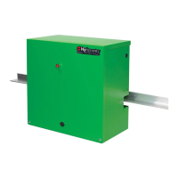
Explanation of how the Hy-Security hydraulic gate operator system works.

Accessory Compatibility Overview

Information on compatibility with access control and entrapment devices.

Pedestrian Entrapment Protection Requirements

Guidelines for protecting pedestrians from entrapment hazards with gate systems.

Installation Preparation Checklist

Gate Operator Installation Steps

Mechanical and Hydraulic Adjustments

Using the Smart Touch Controller

Smart Touch Controller Configuration

Setting Operator Handing and Usage Class

Configuring the gate operator's handedness and UL usage class.

Wiring Control Inputs to Smart Touch Controller

Connecting Master and Slave Operators

Smart Touch Controller User Menu Functions

User Menu Options Overview

Detailed descriptions of available functions and settings in the User Menu.

Smart Touch Controller Installer Menu Functions

User Menu Function Descriptions

Installer Menu Function Descriptions

Correctional Facility Wiring Options

Connecting an Interlocked Gate Pair

Wiring procedure for interlocking two gates for correctional facility use.

External Lock Mechanism Connection

How to connect an external solenoid or maglock to the controller.

Gate Secure Position Indicator Output

Connecting a device to indicate the gate's secure position status.

User Programmable Output Relay Options

Clock and Date Functions

Setting the Time and Date

Guide for setting the internal clock and date on the Smart Touch Controller.

UL 325 Entrapment Protection Standards

UL Usage Class Information

Explanation of UL usage classes and their implications for gate operators.

Secondary Pedestrian Entrapment Sensors

Installing Gate Edge Sensors

Installing Photoelectric Sensors

General Information and Compatibility

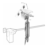
Overview of photoelectric sensor types, compatibility, and UL requirements.

Installation, Configuration, and Connection

Details on sensor mounting, wiring, and controller configuration settings.

Supervised Connection and Photo Eye Function

Explains supervised connections and the operational function of photoelectric eyes.

Sensor Alignment and Retro-reflective Notes

Best practices for sensor alignment and specific notes for retro-reflective systems.

Detector and Loop Fault Diagnostics

Detector Configuration and Anti-Tailgate Modes

Slide Gate Loop Layout

Vehicle Detector Installation Options

Hy-Security Hy-5A Vehicle Detector Installation

Standard 11 Pin Box Type Vehicle Detector Installation

24 hr 7 day Timer Connection

Connecting a Radio Receiver

Remote Release Mechanism

Internal Solenoid Lock Instructions

Internal Solenoid Lock - Elevation

Troubleshooting Gate Movement

Troubleshooting Alerts and Errors

General Maintenance - Hydraulic System

Maintenance Schedule

Manual Release Mechanism Use and Adjustment

DC Powered Gate Operators Special Notes

Wiring and Control for DC Operators

DC Remote Power Package

Battery Connection Diagram (24V-100 A.H.)

Battery Connection Diagram (24V-170 A.H.)

333 Modular Slide Gate Operator

333 Series Pump and Electrical Panel

Wire Size Schedules

Wire Size for Voltage Drop

444 Operator Components and Footprint

Components Breakout - Control Box

Limited Warranty (Hydraulically Powered Operators)

Related product manuals