Do you have a question about the Hy-Security 222 EX and is the answer not in the manual?
Explains the time delay Soft Stop system and optional brake valves.
Details the AWOG soft starting system for smooth acceleration.
Details E Models with hydraulic manifold and adjustable brake valves.
Explains EX Modes with AWOG and brake valves for faster speeds.
Covers DC operators with UPS, sealed batteries, and backup travel.
Details CF models with heavy-gauge cover and locking options.
Explains 333 Modular Operators with separate enclosures.
Covers 444 Operators for heavier gates with larger chassis.
Describes the Smart Touch Controller as the operator's digital brain.
Displays common industry symbols used for safety warnings.
Provides critical safety instructions for designers and installers.
Lists conditions that must be met before installing an automatic gate operator.
Emphasizes that all wheels must be covered for safety.
Covers gate movement, operator placement, and electrical grounding.
Instructs installers to convey key safety and operation points to owners.
Describes the hydraulic operator's drive system and its reliability.
States compatibility with access control and entrapment protection devices.
Advises reading safety information before installation.
Illustrates safety mesh and gate distance from operator.
Highlights the need for cantilever gate wheel covers.
Shows operator and drive rail alignment and shimming.
Details drilling and setting anchor bolts for the operator base.
Instructions for aligning the operator parallel to the gate.
Guidance on mounting the separate enclosure for modular models.
Explains connecting the drive rail to the gate panel.
Details mounting limit ramps for gate travel control.
Describes applying grip tape to the underside of the drive rail.
Explains how to clamp drive wheels and adjust spring tension.
Details connecting primary power, voltage, and grounding.
Instructs checking the primary tap on the control transformer.
Notes AC power routing for 333 type operators.
Details AC power, conduit, and DC circuits for battery operators.
Explains how to set the operator's handing (left/right).
Instructs to replace the blue shipping plug with a breather cap.
Emphasizes controller configuration before external controls connection.
Details adjusting the drive wheel spring compression.
Explains verifying and adjusting drive rail alignment.
Describes adjusting brake valves for smooth gate stops.
Details adjusting the pressure relief valve for maximum system pressure.
Describes the function of directional and quick stop valves.
Details the functions of the five buttons on the controller.
Explains how to navigate menus and change settings.
Describes how to enter the User and Installer Menus.
Guides setting operator handing and UL usage class.
Lists and describes each input terminal and its function.
Provides important notes regarding input connections and supervision.
Details wiring and menu settings for master/slave configuration.
Lists user menu items, defaults, and descriptions.
Provides important notes related to user menu settings.
Lists installer menu items, defaults, and descriptions.
Provides important notes related to installer menu settings.
Explains the automatic close timer setting for the gate.
Configures the constant hold push button close function.
Configures the constant hold push button open function.
Configures gate function during AC power loss on DC models.
Configures radio input for open or open/close operation.
Controls the warning buzzer before gate motion.
Enables forced open alert and automatic gate reposition.
Enables drift closed alert and automatic gate reposition.
Aids photo-eye emitter/receiver alignment.
Sets the 24-hour clock for logging events.
Adjusts the LCD display contrast.
Sets the UL usage class required for operator function.
Sets the gate handing (left/right) for operator function.
Restores all menu settings to factory defaults.
Configures operator as Master or Slave in paired installations.
Sets AC charger or solar for DC battery machines.
Enables the Fire Dept. Open input override.
Enables the Emergency Close input override.
Adjusts the sensitivity of the internal inherent sensor.
Allows inherent sensor to only stop the gate (UL Class 4).
Sets leaf delay for closing in Master/Slave setups.
Sets leaf delay for opening in Master/Slave setups.
Sets the maximum gate run time.
Activates and sets partial open duration.
Configures photo eye close reverse to open.
Configures photo eye open reverse to close.
Configures edge sensor reverse to open.
Configures inherent sensor reverse to open.
Sets photo eye output type (NO/NC) and supervision.
Sets edge sensor input type (NO/NC).
Configures terminal #7 for time clock or interlock input.
Configures OOLD function for pause or full reversal.
Configures IOLD function for pause or full reversal.
Configures vehicle detector logic and anti-tailgate modes.
Configures functions for user output relays 1-3.
Adjusts time delay for gate open alert relay.
Adjusts time delay for loitering alert relay.
Controls the HY-5A Free Exit detector.
Controls the HY-5A IOLD detector.
Controls the HY-5A OOLD detector.
Controls the HY-5A Shadow detector.
Details wiring for interlocked gate pairs in correctional facilities.
Explains wiring for external solenoid locks or maglocks.
Details wiring for gate secure position indicator output.
Provides interlock signal or indicates gate security at full closure.
Commands a 2nd machine to close with a pulsed output.
Indicates full open position, active when open limit is triggered.
Trips a sequenced barrier arm gate operator to open.
Controls an external warning device, syncs with internal buzzer.
Controls external solenoid or magnetic locks.
Signals gate forced open and operator inability to close.
Activates when gate is open longer than user-selected period.
Activates when system is in Safety or Entrapment Mode.
Activates only when system is in Entrapment Mode.
Signals unauthorized vehicle entry without access control.
Interlocks to entry device to prevent pedestrian use.
Annunciates vehicle or indicates loitering when gate is closed.
Activates when gate is near full travel (RPM sensors only).
Reports system errors, faults, or entrapment modes.
Active when the motor is running and gate is in motion.
Normally energized, drops with loss of AC power or charger off.
Triggered when battery power is very low.
Controls flashing lights, except when open limit is triggered.
Guides setting the time and date on the Smart Touch Controller.
Defines types of entrapment protection sensors (A, B1, B2, C, D, E).
Explains UL usage classes (I, II, III, IV) for gate operators.
Details placement for non-contact and contact sensors.
Ensures wiring is protected from mechanical damage.
Ensures sensor signals are not impeded by obstructions.
States sensors must be UL recognized components.
Advises assessing risks to determine sensor placement.
Details mounting and wiring for post-mounted and gate-mounted edge sensors.
Guides setup of edge transmitters and receivers.
Details connecting a commercial radio receiver.
Advises testing reversing edge operation weekly.
Discusses photo eye types and requirements.
States photo eyes must be UL recognized and 24V DC rated.
Details mounting height and placement for photo eyes.
Explains selecting light/dark operate and relay output types.
Details wiring for photo eye receivers and emitters.
Enables supervised connection for fault detection.
Describes photo eye behavior on tripping and reversal.
Guides careful optical alignment of photo eyes.
Provides notes on installation and alignment of retro-reflective systems.
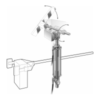
Explains how vehicle detectors work.
Discusses different loop configurations for detectors.
Lists rules for loop placement and wiring in gate applications.
Provides guidelines for the number of wire turns per loop size.
Emphasizes quality installation practices for detector loops.
Recommends detector use for free open and obstruction sensing.
Outlines tests for loop resistance and earth resistance.
Highlights Smart Touch Controller features for detectors.
Lists available vehicle detector input functions.
Details mounting and plugging in the Hy-5A detector.
Explains explaining routing and connecting loop wires to the detector.
Describes automatic tuning and sensitivity adjustment.
Lists configurable vehicle detector functions in Installer Menu.
Details mounting sockets and connecting power to detectors.
Explains connecting detector output and input terminals.
Guides wiring when using multiple detectors.
Emphasizes twisting loop wires for proper function.
Lists alert codes for detector and loop problems.
Explains how to retrieve historical data via RS232.
Guides viewing and changing loop frequency.
Explains how to display and interpret call strength.
Describes modes 1-4 for vehicle detector logic and anti-tailgating.
Guides programming schedules for the 24 hr/7 day timer.
Explains how to change between AM/PM and military time.
Details setting the current hour, minute, and day.
Describes how to review programmed timer schedules.
Explains temporary and continuous manual overrides for the timer.
Guides mounting and wiring a commercial radio receiver.
Details connecting the antenna and setting receiver DIP switches.
Provides instructions for manual operation of the clamp mechanism.
Describes the internal solenoid deadbolt lock.
Explains when the solenoid lock must be activated.
Details notching the drive rail and adjusting the lock enclosure.
Shows wiring for the solenoid lock and indicator switch.
Addresses general gate movement problems and alignment.
Discusses Smart Touch Controller error reporting and voltage issues.
Provides specific troubleshooting steps for common issues.
Lists LCD display codes and buzzer sequences for errors.
Explains factors affecting gate speed and cold weather performance.
Covers fluid level, leak checks, and oil changes.
Advises on oil type and manual gate operation in cold weather.
Discusses cleaning electrical enclosures and troubleshooting.
Details how to adjust the pressure relief valve.
Provides a schedule for checking and maintaining operator parts.
Offers special notes regarding gate hardware and component checks.
Explains how to disengage drive wheels and cautions about spring release.
Details adjusting drive rail height and wheel spread.
Notes on disconnecting DC power and battery storage.
Warns about handling batteries and observing polarity.
Emphasizes using correct wire size for battery connections.
Discusses battery capacity, charging, and lifespan.
Details connecting heavy gage wires between battery and operator.
Explains connecting 14-gage circuits for controls and charger status.
Details four functional choices for AC line power failure.
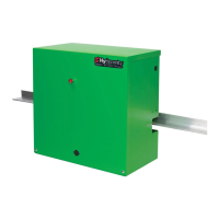
Identifies components of power units.
Lists part numbers for control box components.
Lists and identifies components of the DC power supply.
| Model | 222 EX |
|---|---|
| Category | Gate Opener |
| Max Gate Length | 20 ft |
| Horsepower | 1/2 HP |
| Operating Temperature | -15°F to 158°F (-26°C to 70°C) |
| Max Gate Weight | 1000 lbs |
| Gate Weight Capacity | 1000 lbs |
| Safety Features | Obstruction Sensing |