USER MANUAL - L6A, L6P, LS18A & LS218A POWERED LINE ARRAY
PAGE 13PAGE 12
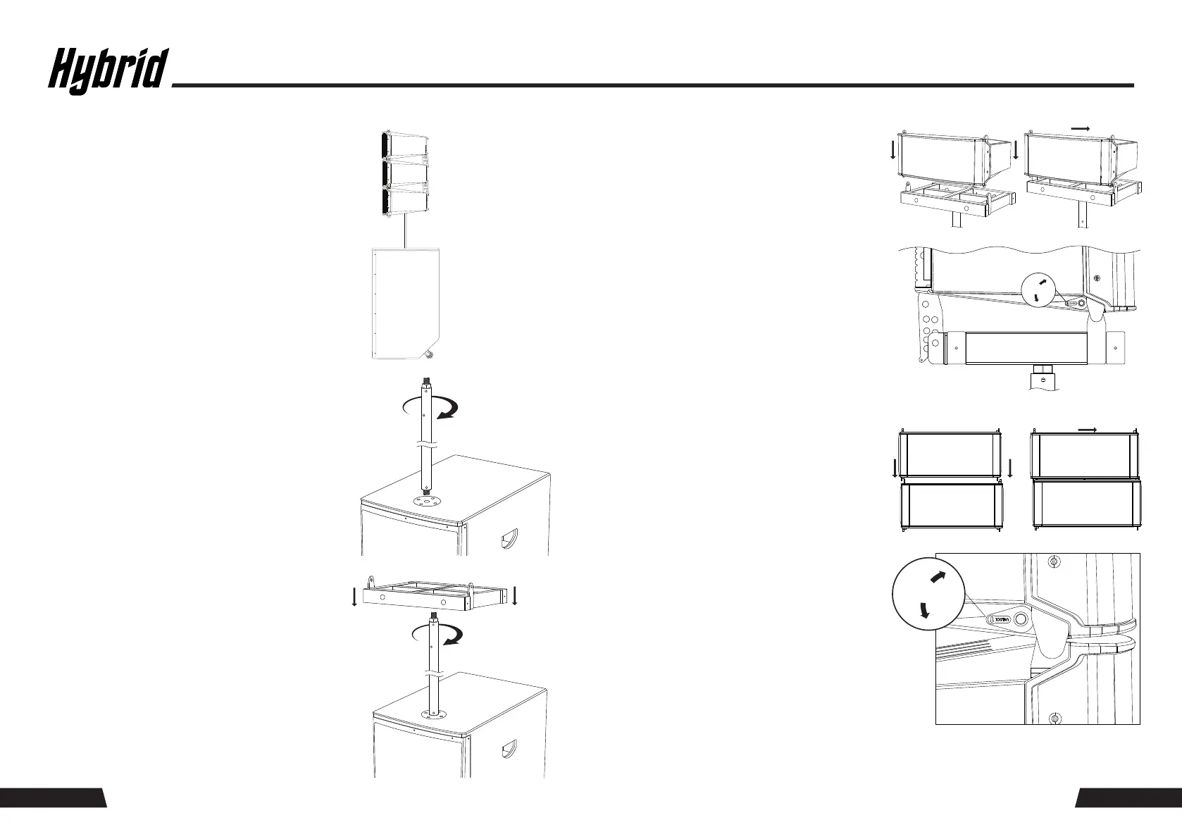
Place the Hybrid LS218A powered sub-bass
speaker on the floor.
LOCK
UNLOCK
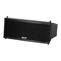
L6P
L6P
M20 THREAD + LOCKNUT
M20 THREAD
M20 TOP PLATE
LS218A
L218P 350MM POLE
L6A
LS218A
M20 THREAD + LOCKNUT
LS218A
L6F
L18P 350MM
GROUND-STACK WITH AN LS218A
1:
2:
3:
Attach the Hybrid L218P (350mm) pole to the
LS218A sub-bass cabinet by screwing tightly
the end with the shorter M20 thread onto the
integrated M20 top plate on the cabinet.
Attach the Hybrid L6F fly frame to the opposite
end of the Hybrid L218P pole by screwing the
longer M20 thread onto the integrated M20
threaded hole on the frame. Once the frame is
completely screwed in, place the frame in the
desired horizontal position and tighten the lock
nut provided on the L218P pole.
Splay Bar
Fly Frame
L6F
L6F
L6A
L6A
Locking Machnism - Locked Postion
4:
Align the front-end rigging holes of the
Hybrid L6P with the front-end rigging holes
of the L6A. Slide the L6P cabinet to the
right until the units are correctly coupled.
Activate the locking mechanism located on
the front end of the L6P.
Lift the rear of the L6P cabinet and align
the desired angle of the L6A integrated
splay bar with the fly frame using the
quick-release self-locking pins attached to
the L6A.
Locking Machnism - Locked Postion
Lift the rear of the L6P cabinet and align
the desired angle of the L6A integrated
splay bar with the fly frame using the
quick-release self-locking pins attached to
the L6A.
5: Align the front-end rigging holes of the
Hybrid L6P with the front-end rigging holes
of the L6A. Slide the L6P cabinet to the
right until the units are correctly coupled.
Activate the locking mechanism located on
the front end of the L6P.
LOCK
UNLOCK
L6A
L6A
L6P
L6P
PAGE 13PAGE 12