3.3
BLADE GUIDE ADJUSTMENT
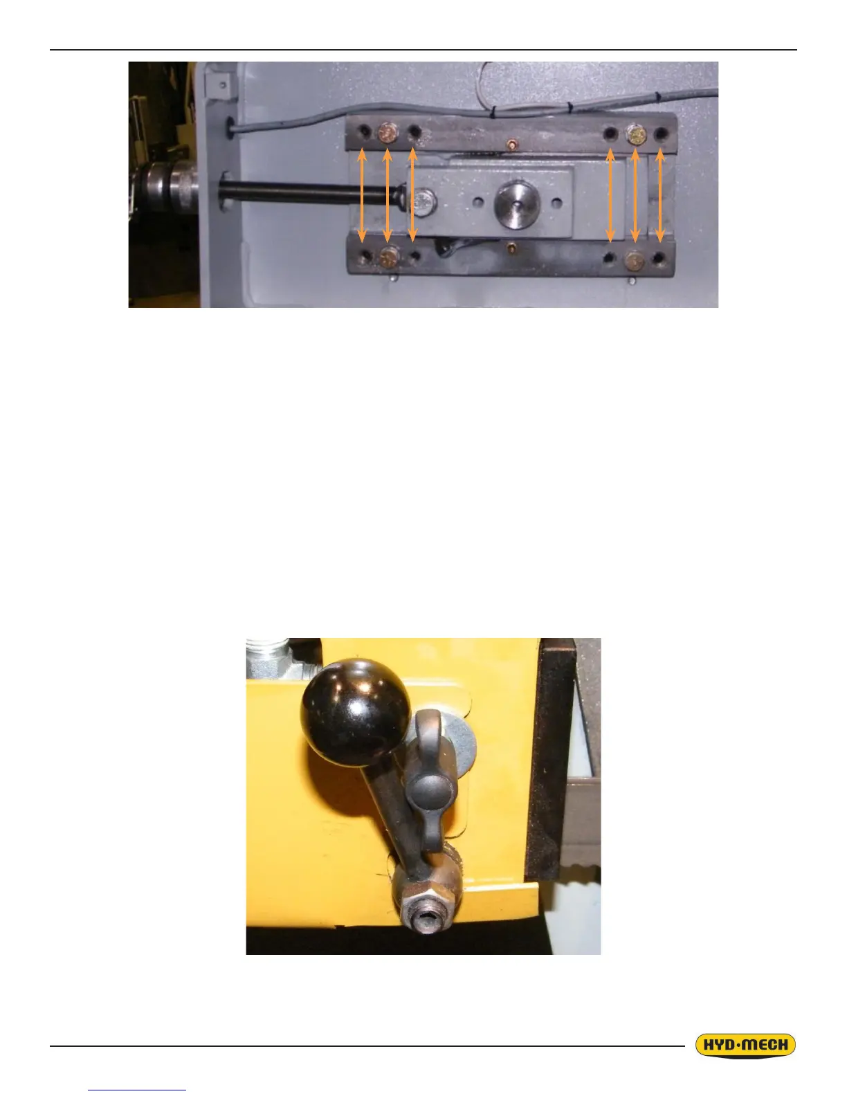
At the bottom of the guide arms are the carbide blade guide assemblies, the photo shows the carbide-locking handle.
These assemblies will need to be adjusted occasionally as the carbide pads become worn. To adjust properly, follow this
simple procedure. Loosen the hex nut on the locking handle and loosen the handle. Turn the setscrew clockwise until tight
and then loosen 1/8 turn and tighten the hex nut. This should put just enough pressure on the blade to permit you to push
the blade down approximately 1/8” (3.2mm).
CC A BD D
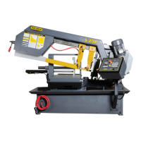
b. DRIVE WHEEL ADJUSTMENT – On the wall behind the drive wheel are two adjusting bolt assemblies
and two hex bolts. Loosen all four of them with a ¾” socket and turn the larger hex head bolts ¼ turn with
a 1 1/8” socket and extension and then tighten the two bolts in the assemblies. Then tighten the two hex
bolts at the left. Turning the 1 1/8” bolts clockwise will pull the blade onto the wheel and turning counter
clockwise will push the blade off. Each ¼ turn will move the blade approximately .02”.
10. Check the blade brush adjustment to be sure the blade is being cleaned properly.
 Loading...