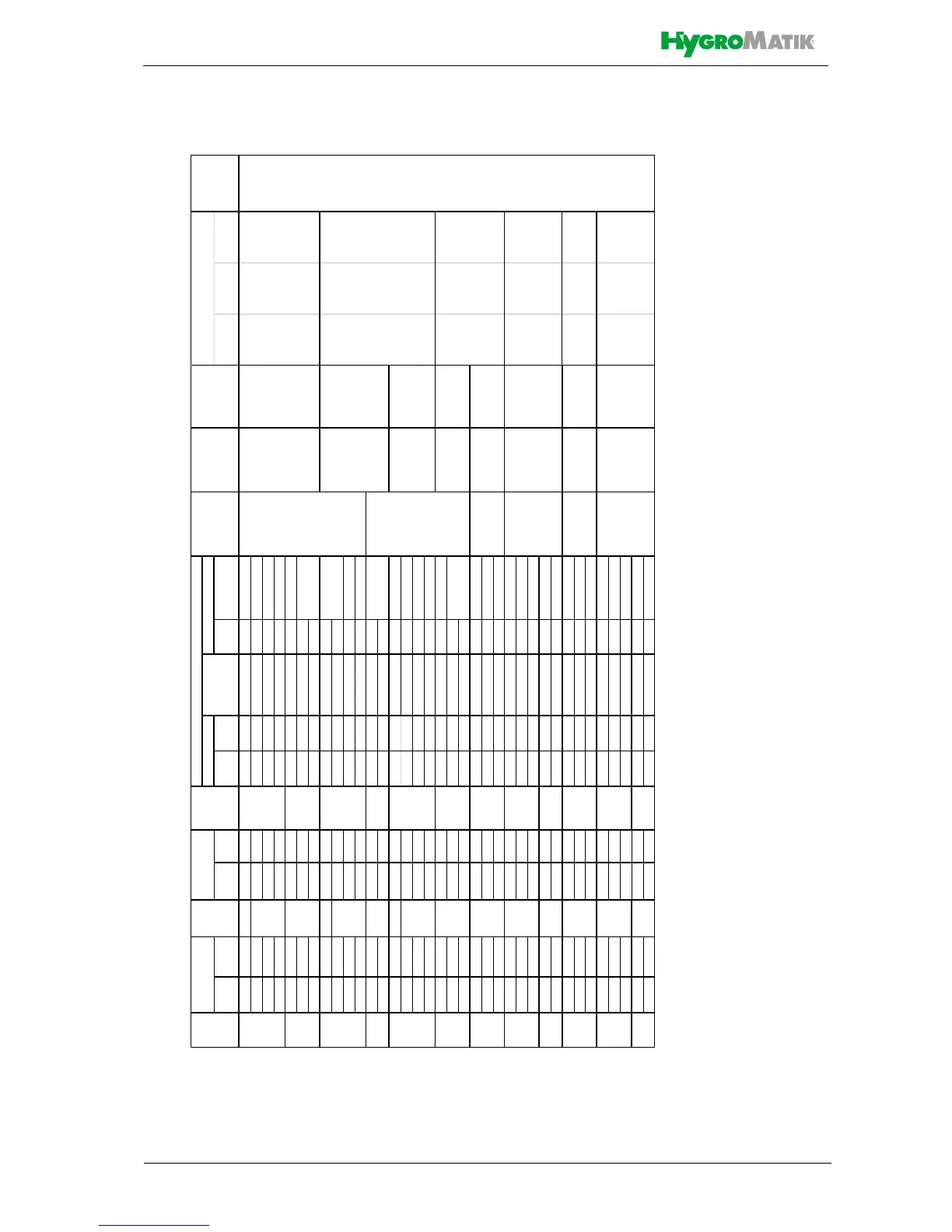
from to from to from to Qty. Rating [A] *)
208 240 1 9.2 10.6 3.1 3.6 15 1
208 240 10.0 11.5 3.4 3.9 9.4 3 15
440 480 10.5 11.5 3.6 3.9 4.7 3
575 600 10.8 11.3 3.7 3.8 3.7 3 5 16/35.3 21/46.3
208 240 15.9 18.3 5.4 6.2 15 3
440 480 21.1 23.0 7.2 7.8 9.4 3
575 600 21.7 22.6 7.4 7.7 7.4 3
208 240 1 18.3 21.2 6.2 7.2 30 1
208 240 30.7 35.4 10.4 12.1 29 3
440 480 31.6 34.4 10.7 11.7 14.1 3
575 600 32.5 33.9 11.1 11.5 11.1 3 15
440 480 42.1 45.9 14.3 15.6 18.8 3
575 600 43.3 45.2 14.7 15.4 14.8 3
208 240 1 36.7 42.3 12.5 14.4 60 2
208 240 51.1 59.0 17.4 20.1 48.3 6 60
440 480 52.6 57.4 17.9 19.5 23.5 3
575 600 53.9 56.2 18.3 19.1 18.4 3 20
208 240 61.4 70.9 20.9 24.1 58 6 60
440 480 63.2 68.9 21.5 23.4 28.2 3
575 600 64.7 67.5 22.0 23.0 22.1 3
208 240 63.5 73.3 21.6 24.9 60 6 65
440 480 84.3 92.0 28.7 31.3 37.65 3
575 600 86.3 90.1 29.4 30.7 29.5 3 35
208 240 102.4 118.1 34.8 40.2 96.7 6 125
440 480 105.5 115.1 35.9 39.2 47.1 6
575 600 107.7 112.4 36.7 38.2 36.8 6 40
440 480 137.1 149.5 46.6 50.9 61.2 6 65
575 600 140.2 146.3 47.7 49.8 47.9 6 50
208 240 127.0 146.6 21.6 24.9 60 12 65
440 480 168.6 184.0 28.7 31.3 37.65 6
575 600 172.7 180.2 29.4 30.7 29.5 6 35
208 240 204.8 236.3 34.8 40.2 96.7 12 100
440 480 211.0 230.1 35.9 39.2 47.1 12
575 600 215.4 224.8 36.7 38.2 36.8 6 40
440 480 274.1 299.0 46.6 50.9 61.2 12 65
575 600 280.4 292.6 47.7 49.8 47.9 12 50
**) External width and depth dimensions. Height including drainage nozzles
28/61.7 49/108
33/72.8 70/154.3
50/110.2 92/202.8
75/165.3 147/324.1
*) 1.1-fold power consumption after full blowdown. Observe actuation characteristics of automatic circuit-breakers. If necessary, select the next higher circuit-breaker level.
31
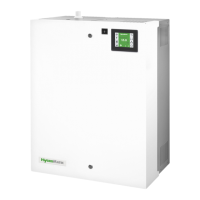
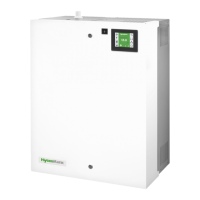
FLE40
60
70
FLE50
1
FLE30
31
FLE65
31
FLE130
2
FLE80
23
23
FLE100
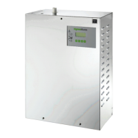
FLE25
1
3
FLE20
3
FLE10
1
FLE05
1
FLE15
1
3
3





 To Next Page