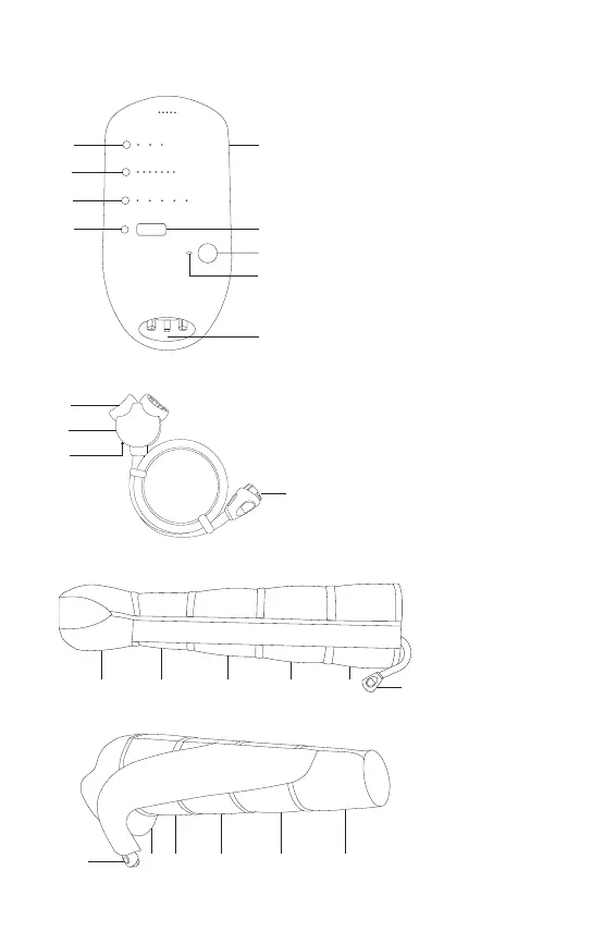
ILLUSTRATIONS
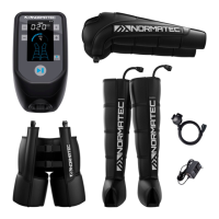
Normatec 3 Control Unit (single-person use only)
Normatec 3 Hose
Normatec 3 Leg Attachment (single-person use only)
1. Power button
2. Attachment selection button
3. Pressure level button
4. ZoneBoost
™
button
5. Time adjustment button
6. Display screen
7. Start/Stop button
8. Bluetooth
®
status indicator
9. Air outlet and power inlet
9
1
2
3
4
5
6
7
8
1. Junction box air outlets
2. Junction box
3. Blocking plug
(on the underside of the junction box)
4. Connector
1
2
3
4
1 - 5. Zones
6. Attachment
connector
321 4 5
6
1 - 5. Zones
6. Attachment
connector
2 13456
Normatec 3 Arm Attachment (single-person use only)