Hypervolt Home 3.0 Quick Start Guide Draft V1.0
Incoming Supply Connections - LIVE, NEUTRAL & CPC (Earth) We
recommended using stranded cables with ferrules. Tighten to 2.3 Nm.
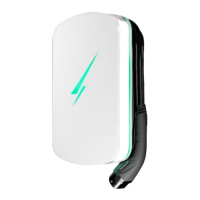
Tethered Cable Connections - This is where the tethered car charging
cable is connected. If you replace this cable remember to put the Blue &
Brown wires back through part 8.
CP Connection - This is where the control pilot from the car charging
cable is connected. It goes in the right side, push the tab to insert.
CT Connection - The CT clamp supplied should be connected here,
extend the cable as necessary using HyperConnect or CAT cable. Use
the Left plug for ALM, The Right Plug is for Additional monitoring (see
main manual).
RJ45 Connection - For a hardwired internet connection plug in here. You
only need to use the Orange & Green pairs of a CAT cable in the standard
T- 56 8B c on figuration.
ALM Adjustment Dial - For setting the Automatic Load Management.
(See page 4)
Derating DIP Switches - For hard setting the Maximum charging limit
(See page 4). Soft set in the App.
Sensing Device (RCD-DD) - Internal 6mA DC sensor. You must fit an
external AC Sensing “A” Type RCD or RCBO (40A Recommended).
LED Front Plate Connection - This is where the LED lights plug in
Cut for Rear Entry Gland - Drill out if required, 25mm Max Ø, seal
accordingly. Original entry hole must be sealed if this one is used.
Main Brain - Where all the HyperMagic happens.
HyperConnect Cable - Live, Neutral & CPC + CAT 5
Additional Cable Entry - Drill out for Band 1 Cables, 20mm Max Ø,
 Loading...