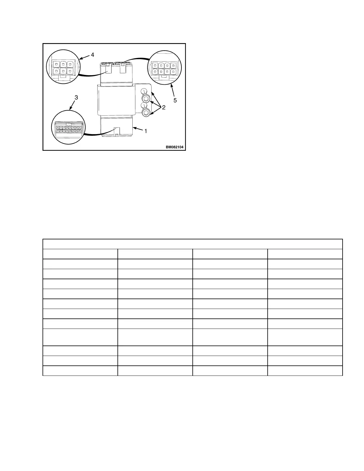
1. CONTROL MODULE
2. MOUNTING HARDWARE
3. CONNECTOR A = 16WAY
4. CONNECTOR B = 6WAY
5. CONNECTOR C = 8WAY
Figure 7. Control Module Connectors
5.
Reconnect 6way connector B, check pin 9 on
connector A for +5V.
6.
If there is no voltage at A9 (+5V), then trouble-
shoot the module. See the Troubleshooting
Manual section.
7.
If the voltages are proper readings (in Step 4
and Step 55), then check inputs at connector A
while activating each function.
NOTE: Voltage should be present at A3, A4, A5, A6
and ONLY while activating the corresponding
function. See Table 2.
8.
If the input values differ from those in the ta-
ble, troubleshoot the control handle compo-
nents, controller, and wiring. Make any neces-
sary repairs, and recheck the input values.
9.
If the input values are correct, replace the con-
trol module. See Remove.
NOTE: PC Service Tool may be used to check com-
munication between control handle, control module,
and traction controller. See the Troubleshooting
Manual section.
Table 2. Input Connector A
16 Pin Connector A
A1 DI1 First Digital Input BS
A2 DI2 Second Digital Input SR
A3 DI3 Third Digital Input Horn
A4 DI4 Fourth Digital Input FWD
A5 DI6 Fifth Digital Input REV
A6 DI6 Sixth Digital Input Raise
A7 DI7 Seventh Digital Input Los1
A8 DI8 Eighth Digital Input Los2
A9 PPOT Positive of AI1, AI2, AI3,
AI4, AI5, AI6
A10 AI2 Second Analog Input
A11 AI3 Third Analog Input
A12 NPOT Negative of Analog Inputs
2200 SRM 1632 Repairs
11
 Loading...