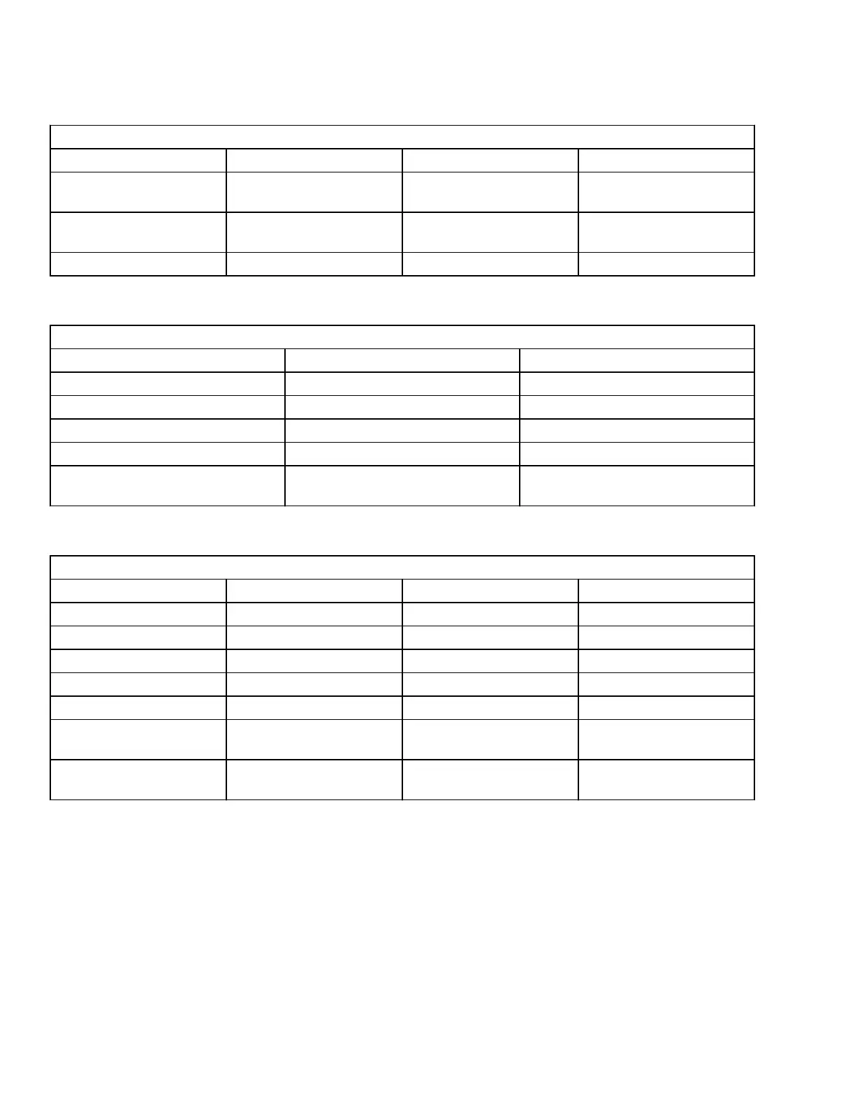
Table 2. Input Connector A (Continued)
16 Pin Connector A
A13 AI4 Fourth Analog Input
A14 +BATT +Battery, Short Circuit to
CNB#5
A15 COMMON Positive of all the Digital
Inputs
Common Microswitch
A16 -BATT -Battery Battery Negative
Table 3. Input Connector B
6 Pin Connector B
B1 CAN LOW Low Level CAN-BUS Voltage I/O
B2 -BATT -Battery
B3 +KEY Key Input
B4 CAN HIGH High Level CAN-BUS Voltage I/O
B5 +BATT +Battery, Short Circuit to CNA#14
B6 SAS Internal Connected to DI1 With a
100 Ohm Resistance
Table 4. Input Connector C
8 Pin Connector C
C1 DI9 Ninth Digital Input Tilt Up
C2 AI1 First Analog Input
C3 NPOT Negative of Analog Input
C4 DI10 Tenth Digital Input Tilt Down
C5 DI14 Fourteenth Digital Input Reach Out
C6 DI11 Eleventh Digital Input Side Left
C7 DI12 / AI5 Twelfth Digital Input /
Fifth Analog Input
Side Right
C8 DI13 / AI6 Thirteenth Digital Input /
Sixth Analog Input
Reach In
Remove
1.
Turn the key switch to the OFF position and
disconnect the battery.
2.
Remove drive unit compartment covers for ac-
cess to the electrical components. See the sec-
tion Periodic Maintenance 8000SRM1635.
3.
Discharge the capacitors. See Discharging the
Capacitors in this section.
4.
Disconnect all connectors from the control mod-
ule.
5.
Remove capscrews, lock nuts, and washers se-
curing control module to the frame. See Fig-
ure 8.
Repairs 2200 SRM 1632
12