Do you have a question about the Hyster D435-R2.0 and is the answer not in the manual?
Provides guidance on navigating and utilizing manual sections and symbols.
Explains safety symbols and their meanings for hazard identification.
Details how to follow reverse procedures for truck installation.
Outlines essential personal protective equipment and safety precautions.
Details requirements for a safe working environment and operational practices.
Presents torque specifications for various screws, nuts, and fittings.
Describes the correct procedure for applying female fittings with and without O-rings.
Lists conditions requiring immediate disconnection and replacement of pipes.
Details essential checks before installing flexible hoses.
Provides guidance on avoiding pipe twisting and ensuring adequate curvature.
Identifies specific wrenches for hydraulic couplings with their codes.
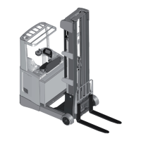
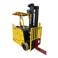
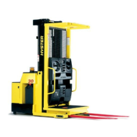
Overview of the Hyster retractable truck range and its systems.
Illustrates different perspectives of the Hyster truck.
Details truck identification data plates and residual load plates.
Locates the mast serial number and truck documentation storage.
Presents detailed technical specifications and dimensions of the trucks.
This manual provides technical information for Hyster service centers, specifically for a range of retractable trucks. It is intended for specialized technicians within the Hyster service network, offering guidelines for correct maintenance and operation. The manual emphasizes the importance of adhering to instructions to prevent damage, injury, or even fatalities. It serves as a supplement to the general use and maintenance manual, focusing on the technical aspects of servicing these machines.
The retractable trucks covered by this manual consist of seven models with nominal load capacities ranging from 1400 kg to 2500 kg. These trucks are designed for various material handling tasks, offering robust performance and stability.
The electrical system of these trucks utilizes three-phase AC alternate current technology for all motors, including the traction, steering, and pump motors. This advanced technology ensures efficient operation. High battery efficiency is achieved through regenerative inversion and release braking, which recover energy during deceleration and braking. The electronic controls, including VCM, ACE2 Traction, ACE2 Pump, and EPS ACW, communicate via a CAN-Bus system (Controller Area Network Bus). To enhance efficiency, reliability, and independence of the modules, two separate CAN-Bus lines are integrated into the system. This dual-line setup ensures robust communication and control throughout the truck's electrical components.
The hydraulic system is powered by a 14 kW pump motor, delivering excellent performance. It incorporates proportional solenoid valves for precise control over various operations. These operations include carriage out/return, lifting/lowering, fork tilting, and side shifting. The proportional valves allow for smooth and controlled movements of the actuators, contributing to the overall efficiency and safety of the truck's hydraulic functions.
The masts of these trucks are designed with a three-stage configuration: external, middle, and internal. This multi-stage design provides the necessary rigidity and stability for lifting heavy loads to significant heights. Depending on the model, the forks can reach maximum heights between 5 and 12 meters. The lifting cylinders are single-acting plungers, which are integral to the mast's lifting mechanism, ensuring reliable vertical movement of the forks.
The manual outlines important safety rules and guidelines for using the trucks and their components. It stresses the need for personal protective equipment in situations requiring it and highlights the risks associated with moving parts, oscillations, and unsecured materials during lifting operations. Operators are advised against wearing loose clothing or jewelry that could get caught in moving parts. Cleaning, lubrication, or maintenance work should never be performed with the battery connected. When using compressed air for cleaning, protective goggles with side protection are mandatory, and air pressure must not exceed 1 bar.
At the workplace, technicians must ensure all work tools are efficient and ready for use, keeping work surfaces clean and free of debris. Sparks, naked lights, and cigarettes must be kept away from fuels and battery gases. The work area should be well-ventilated, illuminated, dry, and clean, with any puddles or oil stains removed. Lifting equipment and devices must be capable of sustaining the load stably. Non-flammable and non-toxic trade solvents should be used instead of gasoline, diesel fuel, or other flammable liquids for cleaning. When working outside, the machine should preferably be on a level surface and blocked. If working on a slope is unavoidable, the machine must be blocked and moved to a level area as soon as possible. Batteries must be disconnected, and controls labeled to signal ongoing work. Servicing should not be performed with persons at the controls unless they are accredited operators assisting with the task. Only prescribed coupling points should be used for towing, ensuring pins and bolts are firmly secured. Heavy parts must be lifted with adequate capacity equipment using lifting eyebolts, ensuring no one is near the load. Twisting chains or metal ropes should be avoided, and bent or damaged ones must not be used. Safety gloves are required for handling chains and ropes. Rags soaked in grease or oil, which pose a fire hazard, must be stored in closed metal containers.
The manual provides detailed instructions for maintenance, including torque settings for screws, nuts, and fittings. It specifies the use of LOCTITE 270 for securing threaded matings. If bolts are difficult to unscrew due to LOCTITE 270, gentle heating (up to 50°C) is recommended to eliminate its effect, rather than using extensions on tools. LOCTITE 270 should be reapplied in moderate quantities (30% of the mating surface) during installation. The correct torque setting is crucial for the security of threaded couplings and the overall safety of the machine. Tables are provided with torque settings for different classes of bolts.
For battery maintenance, it is essential to ensure both ends of the cables are correctly connected (+ to + and - to -) before use. Short-circuiting the terminals must be avoided. During charging, the battery compartment should be uncovered for effective ventilation, and plugs should be removed, as the gas released is highly flammable. Battery charge should never be checked by placing metal items on the terminals. Before any action, it is important to check that no elements are shorted. The battery must always be disconnected before working on the electrical system. For battery chargers and similar equipment, only auxiliary power sources with an effective ground connection should be used to prevent electric shocks. When checking fluid passing through a small orifice, a card or piece of wood should be used to avoid skin penetration, as the fluid can have sufficient force to cause injury. Specific instruments should be used for checking system pressure.
Regarding belts, ropes, and suspension elements, a record of all used components, their characteristics, and identification plate data must be maintained. Components with lost identification plates should not be used. Belts, ropes, or suspension elements must always be of suitable dimensions, considering the lifting angle and any load unbalancing. The bells on suspension elements must be sized proportionally to the overhead traveling crane's hook and allow easy movement. The load should always rest in the hook's race, and the tip of the hook should never be loaded. Sudden operations that can jerk ropes and belts should be avoided during lifting. Ropes and belts should never be twisted, and knots are not permissible. They must be protected from sharp edges. When moving with no load, hooks should be hung in the bells with safety ones closed to prevent impact and accidental hooking.
For unbalanced loads, it is advised to downrate the load capacities of lifting elements as a precaution: slings with 2 booms should be considered as 1 boom, and slings with 3 or 4 booms as 2 booms. Belts, ropes, and suspension elements should be periodically examined according to current legislation and replaced if components show deformation, cracks, hollows, cuts, abrasions, or if wear exceeds 10% of original dimensions, or if the sling shows signs of overloading.
Instructions for installing flexible hoses and fittings include a thorough inspection. A pipe must be disconnected and replaced immediately if there is a shift of the connector, damage, cuts, or abrasions on the surface layer, hardening or stiffness, burns or cracks due to heat exposure, cracks, damage, or bad corrosion on the connector, leaks along the pipe or at the connector, permanent creases, compression, flattening or twists, or blisters, softening, or wear of the external coat. Before installation, flexible hoses must be inspected for correct type, size, reference code, length, and absence of debris, blockages, bubbles, peeling of the outer layer, or other visible defects. Pipes should not be twisted, as this can cause bursting under pressure. An adequate radius of curvature is necessary to prevent constriction and collapse, as the life of the assembled pipe decreases significantly below the minimum radius of curvature. Pressure changes can cause length variations (up to +2%), so a slightly greater length than required is wise to compensate. Special wrenches are specified for hydraulic couplings, with different codes for various sizes (C8-C10, C12, C16).