5
signals from the lift pump control board. Outputs
from the steering angle board connect tothe lift
pump contactor coil. The lift pump contactor is
energized when the drivers (electronic relays) in the
steering angle board complete the circuit on the
negative side of the coil.
3. Provides protection against shorted pump
contactor coils.
(Contactor controlled lift pump motor only.)
If the current draw of a lift pump contactor coil is
excessive, the output driver will turn off to protect
the steering angle board. Normal operation is
automatically restored when the short is removed.
4. Provides lift interrupt when the signal from the
traction SCR card (PA2) is removed.
(Contactor controlled lift pump motor with lift
interrupt option only.)
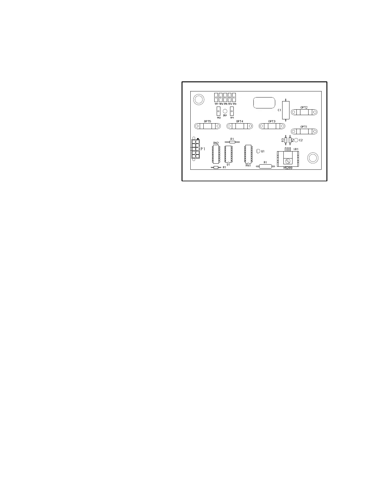
Lift Pump Control Board (See FIGURE 4)
The lift pump control board is located above the hydrau-
lic control valve. Optical switches on the lift pump con-
trol board are utilized to sense the position of the hy-
draulic control valve levers. These optical switches take
the place of conventional mechanical switches. When a
hydraulic control lever is moved from the neutral posi-
tion, the corresponding optical switch is shaded (the
light path is interrupted) and the lift pump is activated.
Optical switches are shaded (the lift pump is activated)
during all functions except lower. An internal voltage
regulator allows dual voltage operation (36 or 48 volts).
The optical switches are used to control both lift pump
control options:
a. Single speed lift pump motor
(Contactor controlled)
b. SCR controlled lift pump motor
1. On the contactor controlled lift pump, the optical
switches on the lift pump control board are connected to
the steering angle control board. A portion of the steer-
ing angle control board is used to process signals from
the lift pump control board. The steering angle control
board is connected to the lift pump contactor coil. The
lift pump contactor is energized when the steering angle
control board completes the circuit on the negative side
of the coil. As a separate function, the steering angle
control board is used to monitor steering tire angle and
supply inputs to the traction control.
With the single speed lift pump, one contactor is used to
control the lift pump motor. Outputs from the logic cir-
cuit are used to energize the lift pump contactor.
FIGURE 4 – LIFT PUMP CONTROL BOARD
2. With the SCR controlled lift pump option, the opti-
cal switches on the lift pump control board are con-
nected to the TB terminals on the lift pump SCR card.
When a hydraulic lever is activated and an optical
switch is shaded, the voltage at the corresponding TB
terminal is dropped to less than 2 volts and the lift pump
starts. Four separate pump speeds are provided with the
SCR controlled lift pump:
a. Slow lift and fourth function (auxiliary # 2)
b. Fast lift
c. Tilt
d. Third function (auxiliary # 1)
OTHER CONTROL COMPONENTS
Following is a short description of the other control
components and their function:
Key switch is in the housing of the instrument
panel and connects battery voltage to all of the
control circuits except the horn.
Accelerator switch assembly is actuated by the
Monotrol pedal or accelerator pedal and is part
of the SRO circuit. If the accelerator switch as-
sembly is closed before the seat switch, the con-
troller will not permit the lift truck to move.
Stop light switch is actuated by the brake pedal
to energize the stop lights on the rear legs of the
overhead guard.
 Loading...