7
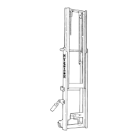
1. PREMIUM INSTRUMENT PANEL
2. STANDARD INSTRUMENT
PANEL
3. GAUGES
4. KEY SWITCH
5. HOUSING
6. INDICATOR LIGHT ASSEMBLY
7. O-RING SEAL
FIGURE 5 – INSTRUMENT PANELS
5
1
2
3
4
6
7
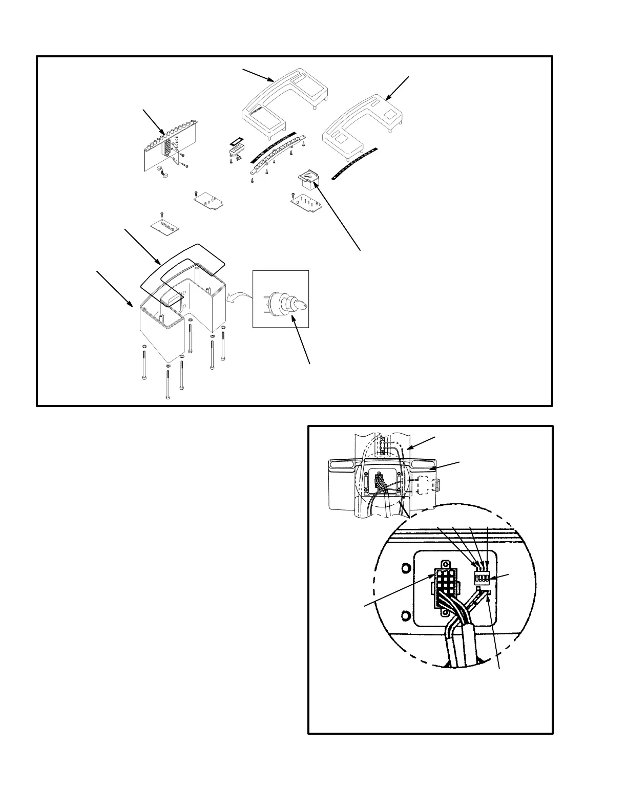
4. Install the replacement panel assembly to the cover
of the steering column and tighten the screws. Install the
connectors and the key switch wires. On the standard
panel, set the DIP switches near the connector for the
panel to the voltage of the lift truck. See FIGURE 6.
Move the DIP switch for the correct voltage to the up
position and all others to the down position. Install the
column cover on the steering column.
FIGURE 6 – DIP SWITCHES
1. STEERING COLUMN
2. INSTRUMENT PANEL
3. ELECTRICAL
CONNECTOR
4. DIP SWITCHES
1340800
2
/
4
36V 48V 72V 80V
1
2
3
4
3
 Loading...