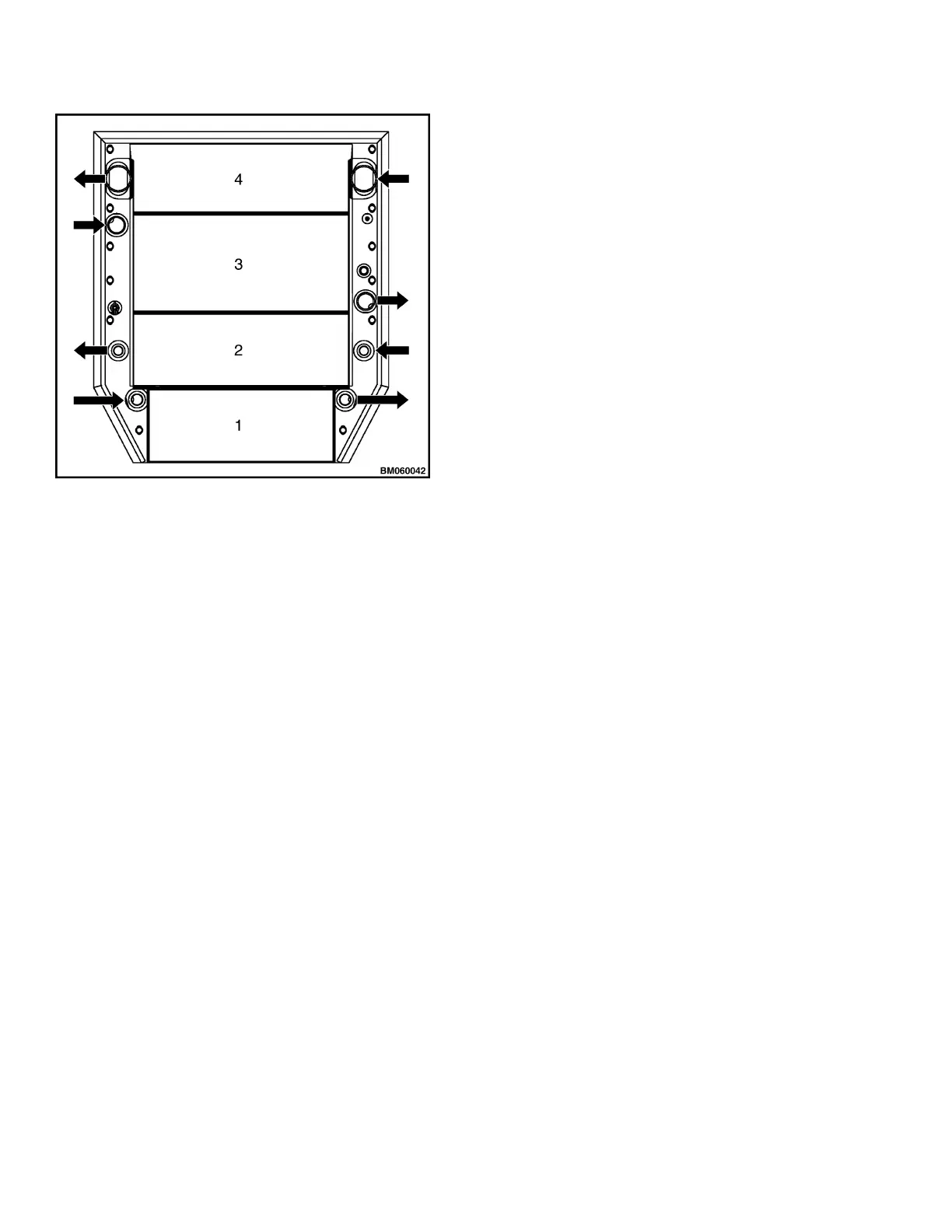
1. TRANSMISSION OIL COOLER
2. HYDRAULIC OIL COOLER
3. ENGINE RADIATOR
4. CHARGE AIR COOLER
Figure 1. Cooling Cores, K007/J019
Fan
The fan pulls air through the cooling core assembly.
On trucks with Tier 3/Stage III A engines, the fan
is directly connected with the fan pulley and turns
proportional to engine speed.
Trucks with Tier 4i/Stage III B engines have a fan
clutch that reduces fan speed when circumstances
allow a lower cooling capacity. The advantage is in
reduced power consumption and a reduced noise
level of the fan.
Fan Clutch
The fan clutch is mounted between fan pulley and
fan. The fan clutch is a viscous coupling that varies
clutch engagement between 30% and 95%, depend-
ing on engine speed and an electrical Pulse Width
Modulation (PWM) signal from the Engine Control
Module (ECM).
Fan Clutch Engagement
The fan clutch consists of a rotor that is connected
with the engine pulley and a housing that carries
the fan. Engagement of the rotor and the housing is
obtained by viscous oil that is present between ro-
tor and housing.
At higher rotation speeds of the rotor, viscous oil is
centrifuged away from the space between rotor and
housing and returns through a bore into an oil
chamber. From this oil chamber, oil returns
through a valve to the space between rotor and
housing.
When the valve closes, oil will NOT return to the
rotor. Existing oil at the rotor will be centrifuged
away, reducing clutch engagement.
By varying the valve opening, the clutch engage-
ment will change.
Maximum engagement is 95%. Lowest engagement
is 30% of engine (pulley) speed.
The valve in the clutch closes against spring force,
when activating the magnet coil in the anti-rotation
bracket. The activated magnet coil attracts the ac-
tuator ring which is connected with the valve
through a pin. The resulting flow of oil changes fan
speed, which is measured by a speed sensor in the
anti-rotation bracket and communicated to the
ECM. Depending on the difference between actual
and required fan speed, the ECM will change acti-
vation of the magnet coil. See Figure 2.
The PWM signal to the magnet coil depends on the
temperature inputs for engine coolant, intake air,
and transmission oil. These inputs are received by
the ECM and result in a programmed signal to the
magnet coil. The actual engagement can be checked
with a laptop through the Cummins programme
called Insite’.
When the magnet coil is de-activated, spring force
will open the valve. This means that in case of an
electric failure, the engagement of the clutch will be
at maximum.
Cooling System 0700 SRM 1595
2





 To Next Page