Clutch engagement is also influenced by actual vis-
cosity of the viscous oil. Engagement is higher at
lower temperatures. Engagement is lower at higher
temperatures. The ECM compensates for differen-
ces in engagement, but at extremely cold tempera-
tures the normally lowest engagement of 30% may
remain at a higher level because of the higher vis-
cosity.
The reaction time for a changed engagement de-
pends on actual viscosity and rotor speed (engine
speed). This is particularly noticeable when com-
paring the start of a cold engine and a warm en-
gine. After cold starting the engine, it will take at
least 30 seconds at high idle before the oil at the ro-
tor has disappeared, disengaging the clutch. The
fan clutch of a warm engine will disengage in less
than 20 seconds after the engine has been started.
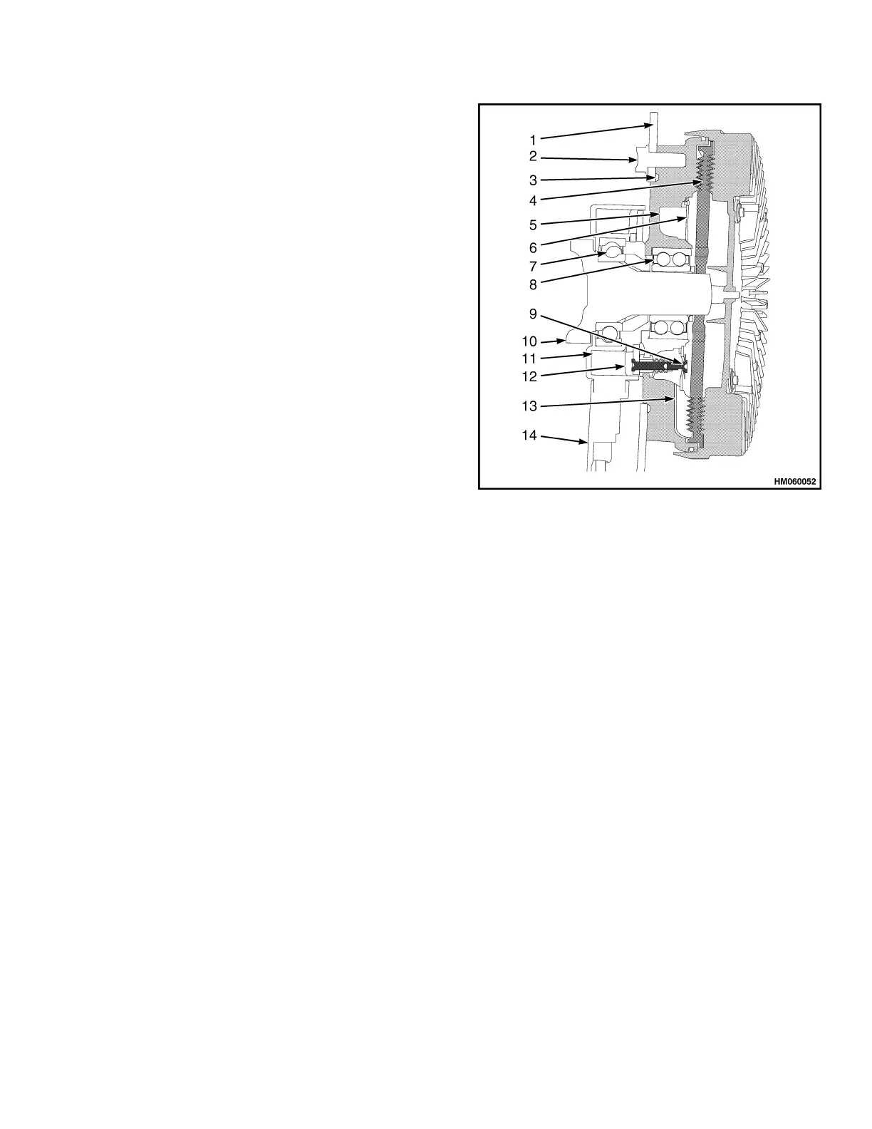
1. FAN FLANGE
2. FAN RETAINER BOLT
3. FAN CLUTCH HOUSING
4. ROTOR
5. OIL CHAMBER
6. SEPARATING WALL
7. COIL BRACKET BEARING
8. CLUTCH HOUSING BEARING
9. VALVE
10. HEXAGON NUT
11. MAGNET COIL
12. ACTUATOR RING
13. RETURN BORE
14. ANTI-ROTATION BRACKET
Figure 2. Fan Clutch
Shroud
The shroud on the cooling core assembly raises the
efficiency of the fan and ensures that air is pulled
through the cooling cores only. Fan efficiency is
raised by a narrow clearance between fan and
shroud. One third of the fan is outside the shroud,
to allow centrifuged air to escape. This increases
the propelled air volume.
The warmed air flows away underneath and at the
front of the truck. Seals between the frame and the
core assembly prevent the recirculation of warmed
air to the suction side of the core assembly.
0700 SRM 1595 Cooling System
3





 To Next Page