Service Manual UHF1 (400-470MHz) Information
115
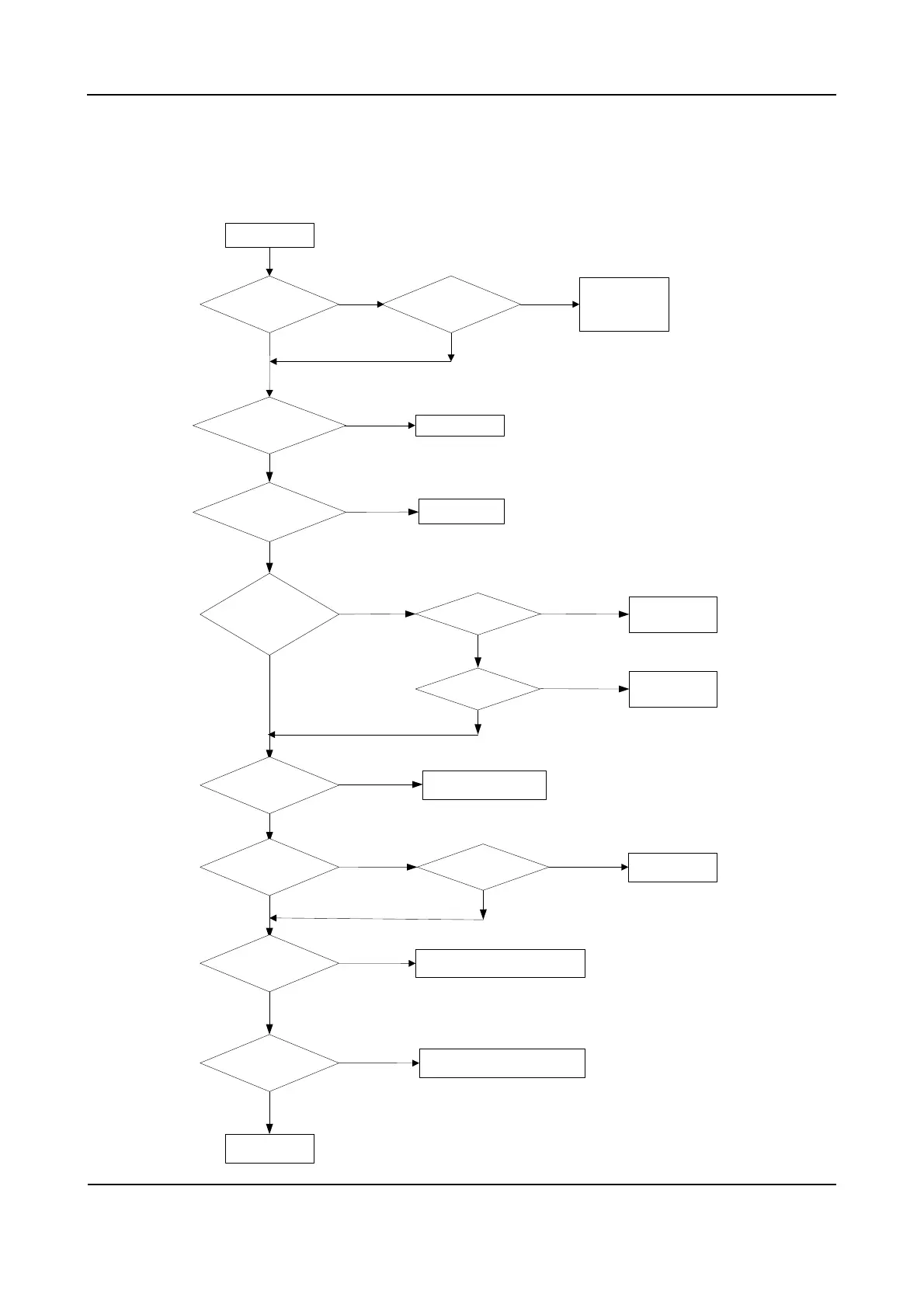
7.8 Troubleshooting Flow Chart
Receiver Circuit
Check Q9001.
The second LO is
normal?[6]
Input IF signal
via U401 PIN47 to check
whether IF sensitivity
is normal?[5]
Check Q403 and
peripheral
components.
Check Q9017
and Q9018.
Check Q9019.
Check Q9001 and the
front-end RF circuit.
No
No
Yes
Yes
Yes
Yes
Yes
Yes
No
No
No
No
No
Check D401 and
other appropriate
components.
No receive
No
Yes
Yes
Check RX VCO.
Yes
No
TP9003 outputs
normally?[10]
Yes
No
Check Z9001, Q9017, Q9018 and
peripheral circuits.
No
Yes
R5V output is normal?[1] 5VRT output is normal?[2]
The static
working point of Q9001 is
normal?[3]
The static
working point of Q9017/Q9018
is normal?[4]
18MHz crystal is
normal?[7]
TP9004 outputs
normally?[8]
TP9005 outputs
normally?[9]
TP402 outputs
normally?[11]
Input signal is normal?[12]
Yes
Completed
No
Check signal frequency, amplitude
and modulation information.
 Loading...