Do you have a question about the Hyundai 20D-7 and is the answer not in the manual?
This document is a service manual for Hyundai forklifts, specifically models 20D-7, 25D-7, 30D-7, and 33D-7. It provides comprehensive technical information and procedures for the maintenance, repair, and adjustment of these forklift models. The manual is structured into several sections covering various systems and components of the forklift.
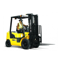
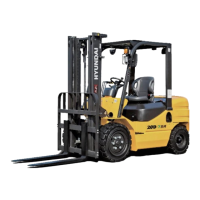
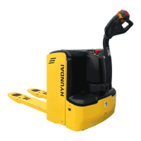
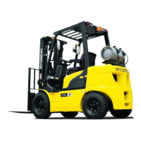
The Hyundai forklifts described in this manual are industrial vehicles designed for lifting and transporting materials. They are equipped with a mast and forks to handle loads, making them essential for operations in warehouses, construction sites, and other industrial environments. The manual details the structure and operation of key systems, including the power train, brake system, steering system, hydraulic system, and electrical system, all of which contribute to the forklift's primary function of material handling.
While the manual doesn't list specific performance specifications like lifting capacity, engine power, or travel speed directly on the introductory pages, it provides detailed breakdowns of the internal components and their functions. For instance, the "MAIN CONTROL VALVE" section (page 6-8) illustrates a complex hydraulic valve assembly with various plugs, springs, and seals, indicating a sophisticated hydraulic system. The "INLET SECTION OPERATION" section (page 6-9) further details the relief valve piston and its associated components, highlighting the precision engineering involved in the hydraulic control. The "TRAVELING BRAKE SYSTEM ASSEMBLY" (page 3-65) mentions a tightening torque of 6-7 kgf·m (43-51 lbf·ft) for a bolt, which is a critical specification for ensuring proper brake function. The "Assembly of carrier assembly" section (page 3-64) refers to spreading Loctite #5127 and #277, indicating specific material requirements for assembly. The "Fasten RING BRG ADJUST" section (page 3-63) specifies a backlash of pinion shaft and ring gear between 0.15-0.2mm (0.006-0.008 in), which is a crucial tolerance for the drive axle's smooth operation and longevity.
The manual implicitly describes usage features through its detailed instructions for removal, installation, and adjustment. For example, the "MAST" section (page 2-2) outlines the process of removing the mast and forks, which are the primary load-handling components. The instructions for handling the forks, backrest, and carriage suggest that these components are designed for robust use and require careful handling during maintenance. The "STEERING SYSTEM" section (pages 5-1 to 5-12) would detail how the steering unit, priority valve, and steering axle work together to provide precise control of the forklift. The "HYDRAULIC SYSTEM" section (pages 6-1 to 6-22) would cover the operation of the gear pump, main control valve, and work equipment circuit, which are essential for lifting and tilting operations. The "ELECTRICAL SYSTEM" section (pages 7-1 to 7-13) would describe the electrical circuit and components, which are vital for the forklift's overall operation, including starting, lighting, and safety features. The "NEUTRAL" and "LEFT TURN" diagrams (pages 5-3, 5-4) illustrate the hydraulic flow paths for steering, indicating that the steering wheel's movement directly controls the spool within the steering unit, directing oil flow to the gerotor for turning. This highlights the hydraulic power steering feature of the forklift.
This service manual is primarily a maintenance guide. It emphasizes the importance of proper procedures for ensuring the quality of repairs and extending the product's lifespan. Key maintenance features include:
In summary, this service manual is an indispensable resource for anyone involved in the maintenance and repair of Hyundai 20D-7, 25D-7, 30D-7, and 33D-7 forklifts, providing the necessary technical information to ensure their safe and efficient operation.