9
INSTALLATION AND OPERATION INSTRUCTIONS
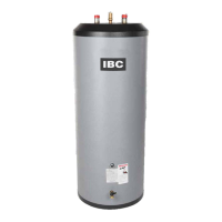
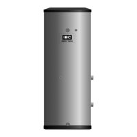
IBC INDIRECT WATER HEATERS - ALL MODELS
The water heater connection labeled “BOILER RETURN” should be piped to the
boiler return piping as close to the boiler as possible and after any ow control or
check valves in the space heating return piping. The use of a union and a shut-off
valve is recommended. The use of a check valve is required to prevent back ow
through the water heater during operation of the space heating system.
Zone Valve System
It is recommended that minimum size 1” pipe and 1” full-port zone valves with a
high CV be used on the water heater zone to ensure adequate ow.
For a space heating system that uses Zone Valves only, see Section 8,
Mechanical Drawing #4. Some important details for Hybrid Systems - see Section
8, Mechanical Drawing #5. The water heater connection labeled “BOILER
SUPPLY” should be piped to the boiler supply piping after the air purger and
before the space heating circulator. Installing the check valve, as illustrated in
the drawing is necessary to prevent reverse ow from the heating system back
through the water heater. Mount the water heater circulator as close as possible
to the water heater, and make sure the ow arrow points toward the water heater.
The use of a shut-off valve is recommended for future service convenience.
The water heater connection labeled “BOILER RETURN” should be piped to the
boiler return piping as close to the boiler as possible and after any ow control or
check valves in the space heating return piping. The use of a union and a shut-off
valve is recommended. The use of a check valve is required to prevent back ow
through the water heater during operation of the space heating system.
4) - Electrical
1. Install electric wiring and grounding in accordance with the National Electrical
code and local regulations.
2. All water heaters are supplied with a temperature sensor that connects to
the IBC control board “DWH S” terminals with standard 2-wire, 18 gauge
thermostat wire. For other boiler makes, an aquastat thermostat is required.
3. Refer to Mechanical Drawings #1, #2 and #3 for separate circulator wiring.
4. Refer to schematics #4, #5 for zone valve wiring.
5. Reference should be made to the Installation Manual for the boiler as well.
Temperature Sensor
The Temperature Sensor supplied with the IBC Water Heater is an NTC
Thermistor type with a resistance of 10,000 ohms at 25°C and β = 3892. IBC
does not recommend using 3rd party supplied sensors. Compatible water
temperature sensors are readily available from your IBC distributor.
The resistance of the temperature sensor varies inversely with temperature. To
test, measure the temperature of the sensed environment and compare with the
value derived from the measurement of the resistance (obtained by connecting a
good quality test meter capable of measuring up to 5,000 kΩ (5,000,000Ω) at the
controller end of the sensor lead).
To obtain a resistance reading, remove power to the boiler. The sensor leads
must be disconnected from the terminal strip while taking the reading. Do not grip
the sensor leads in your hands or place them on or against a conductive surface
or the reading will be compromised. Place multi-meter probes onto the bare wire
ends of the leads and obtain the reading. Compare the reading to the actual
sensor temperature and the resistance value listed for that temperature in Table 4
(below). Do not apply voltage to the sensor (damage may result).
NOTE
The piping drawings in
Section 8 of this manual are
simple schematic guides
to a successful installation.
There are many necessary
components not shown,
and details such as thermal
traps are left out so the
drawings have greater clarity.
We require that our boilers
and tanks be installed by
licensed and experienced
trades people who are familiar
with the applicable local
and national codes. System
design is to be completed
by an experienced hydronic
designer or Engineer.
The application drawing(s)
shown in this manual are only
part of the nished design.
It is absolutely neccessary
to carefully read and follow
these installation instructions,
and just as importantly, the
installation instructions or the
boiler model you are using
with this water heater.
DANGER
DO NOT connect thermistor
sensors to “Therm” terminals
on the IBC control board.
An overheating hazard can
result, potentially causing
serious personal injury and/or
property damage.
WARNING
The Thermistor temperature
sensor supplied with the IBC
water heater is unlikely to be
compatible with other makes
of boiler or controls, and its
use may create a hazardous
condition. DO NOT USE THE
IBC SENSOR WITH OTHER
APPLIANCE MAKES.
 Loading...