1-13
INSTALLATION
SFT 199 TANKLESS WATER HEATER
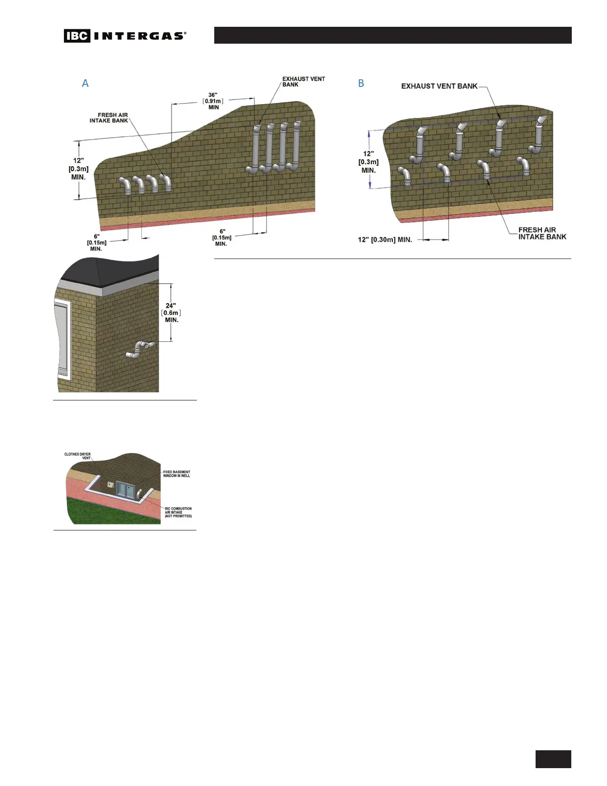
For side venting of multiple units, group all intake terminals together with 6"
(minimum) lateral spacing, and similarly group the exhaust pipes. Place the 2
groups on the same plane of the building (e.g., north facing wall). Place the 2
groups of pipes at least 3' apart (the closest intake and exhaust pipes must be
36" - or more – apart). Use same 12" (minimum) vertical separation (see A in
Figure 12). Alternatively, as long as the units are identical models - intake and
exhaust terminals can maintain a minimum of 12" of separation horizontally from
any exhaust or inlet termination of an adjacent unit (see B in Figure 12). For
alternative group terminations, contact the IBC Factory for written guidance.
Concentric Side Wall Termination Kits
Install the Concentric Side Wall Termination kits:
• On the same horizontal line (not stacked)
• With a minimum vertical separation of 12” center to center
Use caution when installing Concentric Side Wall Termination kits when the outdoor
design temperature is below 5°F / -15°C. Possible blockage of the combustion air
intake increases when the outdoor temperature drops below this temperature.
You must follow the clearances recommended by the vent termination
manufacturer.
Approved concentric side wall termination kits are listed below: (Alternative vent
termination kits must be submitted to IBC for approval prior to installation.)
• Centrotherm – Inno ue #ICWT242 (2” termination) + ICTC0224 (2” transition
to 2 pipe)
• Centrotherm – Inno ue #ICWT352 (3” termination) + ICTC0335 (3” transition
to 2 pipe)
• Duravent – Polypro #3PPS-HK – Horizontal Termination Kit – Concentric
• Ipex #197006 – 3" PVC Concentric Termination kit
• Ipex #197009 – 3" CPVC Concentric Termination kit
Figure 14: Prohibited installation
Figure 13: IBC recommended
minimum vent terminal clearance
under ventilated soffi t
Figure 12: Sidewall vent termination - multiple vent piping confi guration
 Loading...