4-3
MAINTENANCE
SFT 199 TANKLESS WATER HEATER
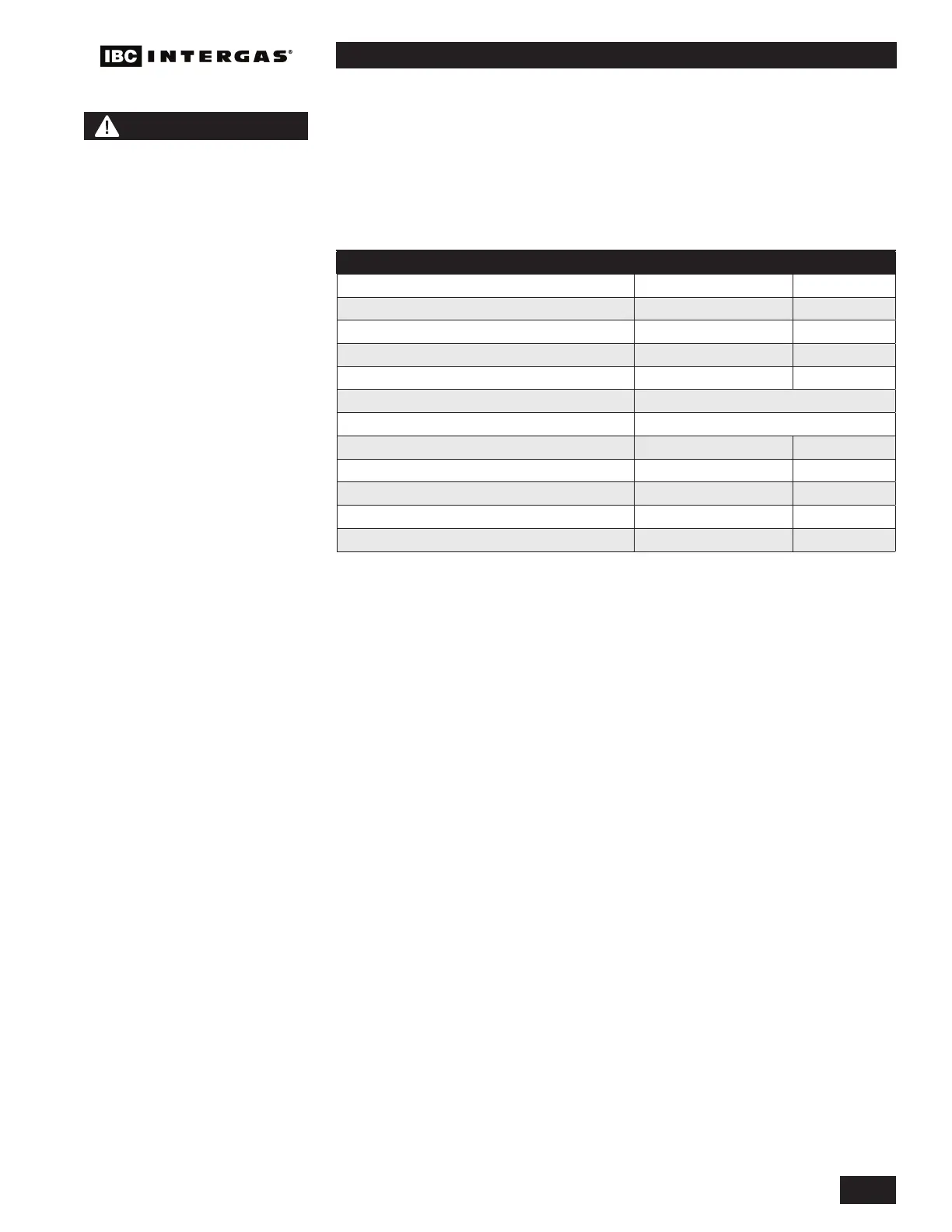
4.1.11 Domestic Hot Water System
Quality of the domestic cold water is very important to the longevity of the unit.
The recommended pH of the domestic water is between 6.5 and 8.5. The internal
domestic water heat exchanger tubing and the ow sensor is subject to fouling if
exposed to hard water (over 1.68 grains of hardness) or has a TDS of 500mg/L or
higher. See Table 13.
DESCRIPTION MAX MIN
Water Pressure 150 psi 40 psi
Programmable water temperature 149°F (65°C) 104°F (40°C)
Minimum Flow Rate to Activate DHW Sensor N/A 0.5 GPM
Acceptable pH range 8.5 pH 6.5 pH
Total Dissolved Solids 500 mg/L
Total Hardness 200 mg/L 11.68 gr/gal
Aluminum 0.05 to 0.2 mg/L
Chlorides 250 mg/L
Copper 1.0 mg/L
Iron 0.3 mg/L
Manganese 0.05 mg/L
Zinc 5 mg/L
Table 13: Domestic Water Quality Guidelines
4.1.12 Fan and gas valve removal instructions
1. Turn off the power and the gas supply to the unit.
2. Remove the front cover, and allow the unit to cool down.
3. Disconnect the electrical plug attached to the fan.
4. Loosen the union nut at the top of the gas valve. Carefully remove the ori ce
and O-ring, and keep in a safe place for re-installation later. Ensure you protect
the gas valve outlet from dust and debris.
5.
Remove the 2 hex nuts connecting the fan to the burner housing, and carefully
remove the fan. You will nd a gasket attached to the fan outlet as well as an
internal check valve. Keep these items in a safe place for re-installation.
6. If the removed fan is to be re-installed, ensure the fan and venturi are clean
and dust free.
4.1.13 Fan and gas valve re-assembly instructions
1. Place the fan gasket on the outlet of the fan housing. The gasket has 2 locator
pins to ensure the gasket does not move during installation.
2. Place the check valve on the fan gasket, and attach the fan to the burner
housing and install the 2 hex nuts. Tighten the 2 hex nuts with a wrench.
3. Insert the ori ce and O-ring between the gas valve outlet and the gas line to
the fan. Tighten the gas valve union nut with a wrench. Ensure that the gas
valve inlet (lower) nut is tight.
CAUTION
Before testing the relief valve,
make certain the discharge
pipe is properly connected to
the valve outlet, and arranged
to contain and safely dispose
of equipment discharge.
 Loading...