INSTALLATION AND OPERATION INSTRUCTIONS
2-12
VFC 15-150 - VFC 45-225 MODULATING GAS BOILERS
10. For all loads, select and enter a Maximum allowable temperature and on/
off Supply Differential Temp. Note these values must be input; they are not
automatically assigned as done within some boiler controls. Ensure the
Maximum takes account of the construction and safety requirements of each
application–e.g.,140°Fmax.fortypicalin-slabradiantoor,foravoidanceof
thermal stress. The Differential shall be set to offer a reasonable temperature
control range (suggested values: 22°F for high mass radiant // 40°F for low
mass baseboards // 30°F for DHW). Ensure that the spread between the
Target and Maximum temps is greater than one half of the Differential (e.g.
foraradiantoorDesign Supply Temperature of 125°F and a Maximum of
140°F,adifferentialof22°F(halfofwhichis11°F)tsnicely.
11. Avoid situations where the Maximum is close or below the potential Target, or
the boiler will cycle off its (software) water high limit.
12. Priority:- where more than one load is present, it is critical that a value be
entered to allow reasonable load scheduling (see Section 2.6.1).
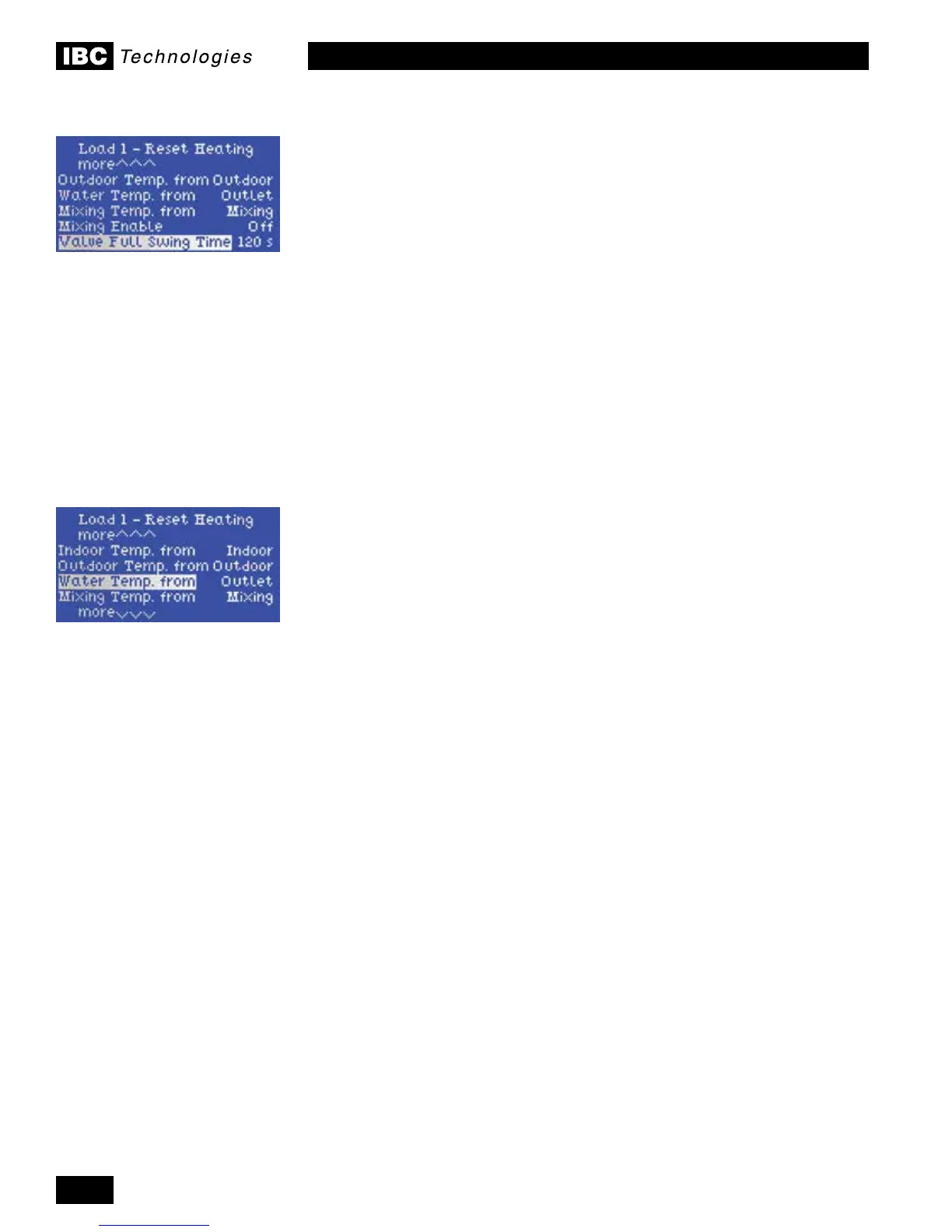
13. At the lower end of the Load 1-2-3 setup screen, there are 4 lines available
for “mapping” of sensor inputs.. For example, “Indoor Temp. from …..Indoor”
indicates that the boiler will look for a signal from an indoor sensor on the
Indoor Sensor wiring contacts. Failing a valid signal, the screen will display
“Indoor Temp. …..Open”, and there will be no effective indoor trim of the
reset curve. These lines do not require amendment at most installation sites.
The mapping feature allows reassignment of the sensor contacts to support
non-standard functions. For example, re-allocation of the Water Temp. signal
from “(boiler) Outlet” to “Secondary Loop” will allow the throttle management
routine to manage a secondary loop temperature rather than the boiler’s own
direct supply temperature. Use this when injecting into a commercial heating:
cooling loop. Another possibility: two separate reset channels – each with its
own indoor trim. Sensor ports open for such re-assignment are DHW, Indoor,
Outdoor and Secondary Loop.
14.Thenal3linesareforthemotorizedmixingvalveoption.Seeseparate
documentation for this.
15. To compensate for altitude at the installation site, use the Altitude adjustment
feature, found in the front Installer Setup menu (several lines below “Heat
Load Conguration”. Key in the altitude – in hundreds of feet above sea
level. For example, an installation at 2,860 feet should be entered as “29” (as
rounded to the nearest hundred).
16. Two lines below Altitudeadjustmentistheeldforamendmentoftheprimary
pumpheatpurgetime.Toshortenthe5minutepost-ringperiod,reducethe
300 second interval to as low as 60 sec. Similar adjustment of secondary
pump run time can be made in the Heat Load Conguration / Congure Load
1,2,3elds(downtozerosec.=off).
17. With software versions 3.10.0 and higher, the controller allows two loads of
compatible temperature settings to be run together. See IBC Technical Note:
Load Pairing for further details.

 Loading...


