INSTALLATION AND OPERATION INSTRUCTIONS
1-28
VFC 15-150 - VFC 45-225 MODULATING GAS BOILERS
NOTE: Sensors connected to any sensor input contacts must be of NTC
Thermister-typewitharesistanceof10,000ohmsat25°Candβ=3892.Wedo
not recommend using 3rd party supplied sensors. Compatible water temperature
sensors and outdoor sensors can be supplied by your IBC distributor.
1.8.6 Thermostat Heat Anticipator
IBC “Therm.” contacts draw no power, so an anticipator setting for the thermostat
is not applicable with the VFC modulating series boilers. In the case of a single
temperature / heat load where zone valves are used to manage individual
thermostatically controlled zones, each room thermostat’s heat anticipator should
be adjusted to the current draw of its associated zone valve.
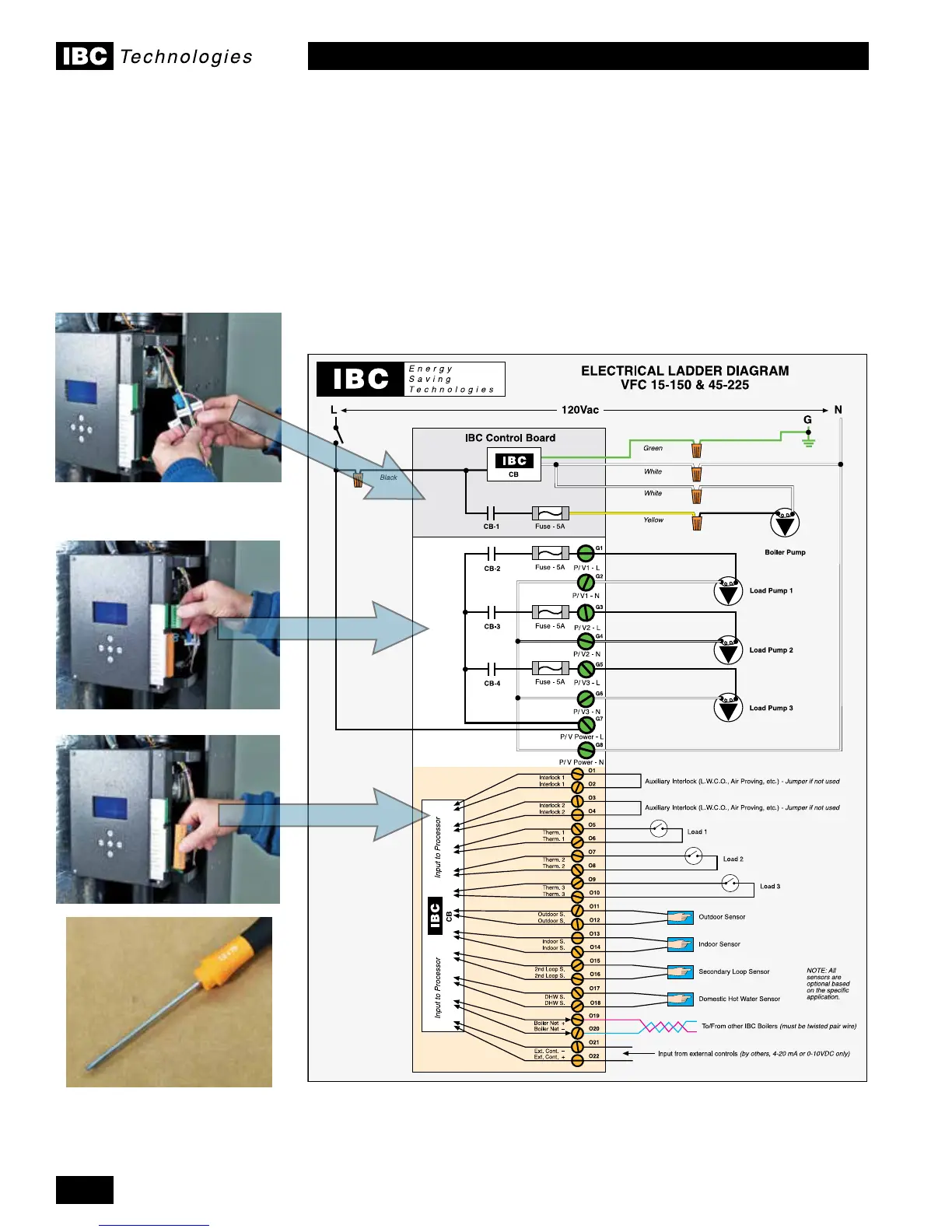
Figure 29: Electrical Wiring Connections (full page ladder diagram at back of this manual)
A 2.5 mm Slot screwdriver is
required for the bottom terminal
strip. Broader or narrower blades
may damage the terminal screws.

 Loading...


