1-27
BOILER SYSTEMS AND OPERATION
VFC 15-150 - VFC 45-225 MODULATING GAS BOILERS
1.8.2 Power Quality and Electrical Protection
Thecontrolboard(forallmodels)isprotectedusingin-lineeldreplaceable
fuses of 5 amp (slow-blow). The control circuit board is further protected using
on-board factory repairable fusing.
The principal exposures to electrical damage:- (a) when wiring of pumps to the
boiler’s pump terminals, avoid screwdriver contact with the metal control cover;
(b) avoid water or solder spray onto fan motor circuitry.
1.8.3 Zone Valve Hook-up
If zone valves rather than pumps are used to manage multiple heating loads, then
24VAC for the zone valves should be provided to the power contacts on the Pump/
Zone Valve Terminal Block. Use a separate transformer – the 40VA unit inside the
wiring box is for internal systems only. The individual load/zone valves are then to
be wired to their associated contacts on the secondary pump/zone valve connector.
Do not confuse such “load/zone valves” with similar valves used to segregate a
singleloadtype(e.g.thoseusedonazonedradiantoor)–seenextsection.
1.8.4 Thermostat / Sensor Wiring
Dry contacts for thermostats for each of 3 loads are provided as marked on the
lower / orange connector strip (e.g. “Therm 1”). Gang lines from a multiple-zoned
load(e.g.offtheend-switchesforeachradiantoorzone)topresentacommon
thermostatsignaltothecontroller.Ensuretherearenodisturbinginuences
on the call-for-heat lines - e.g. no coils to switch an air handler motor. Where
thesezonevalvesareofanon-isolated3-wireconguration,thezonevalveend
contacts must be isolated from the load’s controller thermostat terminal using an
appropriate relay. Required input for enabling the IBC boiler is a dry / mechanical
contact; ensure that triac or other parasitically-powered units are not used.
1.8.5 Other Wiring
Other optional low voltage connections to the control board include:
•Two auxiliary interlocks - for external safety devices as may be required by
some jurisdictions, such as a low water cut-off or a low gas pressure cut-out
(foroff-gridpropane).Aoor-protectingaquastatcanuseoneofthese,to
causeafullboilershutdowninthecaseofexcessoortemperature.
• Contacts for indoor and outdoor temperatures sensors associated with Reset
Heating. A 10K ohm thermister for outdoor reset sensing is supplied with the
boiler, to encourage use of this temperature compensating space heating
techniqueforimprovedcomfortandcombustionefciency.
• One pair for a DHW tank sensor. Connect to “DHW S” (not the respective
Therm. 1,2,3 location) and the boiler will automatically notice and go to a
smart DHW routine
• One pair of contacts for remote secondary loop temperature control.
• One pair (marked BoilerNet) for network connection – this is used for
connecting multiple VFC modulating units for autonomous staging. See
separate Technical Memo for guidance.
• Analpairofcontacts,toreceivea0-10VDC(default)or4-20mAsignal
from an external boiler controller- for direct throttle control. The boiler’s own
sensors act as high limits only. User must enter maximum and minimum boiler
supply temperatures.
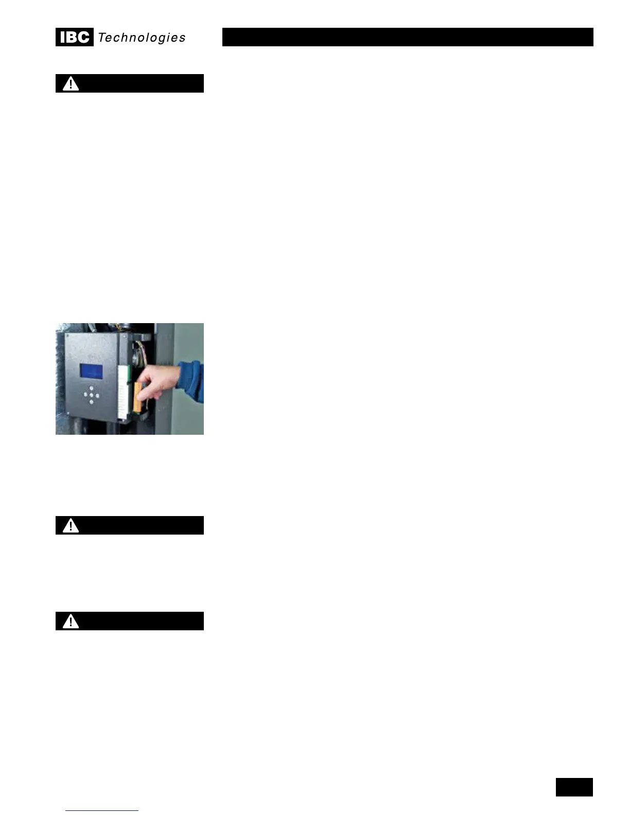
Terminal Strip for:
• Thermostat/switch Inputs
• Sensor inputs
• Auxiliary Interlocks
• Network Wiring
• External Control Signal
NOTE
The IBC control only
recognizes a true dry contact
closure as a call for heat on
terminals “Therm. 1, Therm. 2
or Term. 3. Thermostats and
other devices that use a “Triac”
output cannot be used as a call
for heat without the installation
of an intervening relay with dry
contacts to connect to the IBC
terminal strip.
NOTE
The IBC boiler (like any
modern appliance that
contains electronic
equipment), must have a
“clean” power supply, and is
susceptible to power surges
and spikes, lightning strikes
and other forms of severe
electrical “noise”. Power
conditioning equipment
(surge protectors, APC or
UPS devices) may be required
in areas where power quality
is suspect.
DANGER
Do not connect thermistor
sensors to “Therm” terminals.
An overheating hazard can
result in serious personal
injury and/or property damage.

 Loading...


