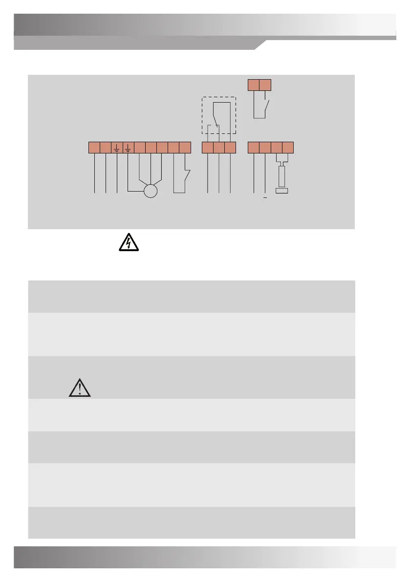
CONNECTIONS
Switch o power before starting work on the equipment.
Recommended tightening torque on terminals 0.5 Nm, max tightening torque 0.8 Nm.
Connection voltage
(L-N-PE)
1x230-240 V +/-15 %, 50/60 Hz.
NOTE! Protective earth must always be connected.
Motor
(U-V-W)
ree-phase induction motor wired for 3x230 V (Delta).
Max 370 W.
Direction of rotation is changed by switching two of the phases.
ermal contact
(T-T)
e thermal contact in the motor should be used to protect the motor
from overheating.
Must be jumped if the temperature switch is not connected.
Alarm relay
(13-14-15)
Closes between 14-15 in the event of an alarm or voltage drop-out.
Max 2 A resistive load / 250 V AC.
Input signal
(2-3)
0-10 V.
Plus connected to terminal 2, minus to terminal 3.
Rotation monitor
(9-10)
White cable connected to terminal 9, brown to terminal 10.
e magnet is installed with south side (S) towards the sensor.
Max. gap 15 mm.
Manual speed
(A1-A2)
Provides set max rpm when closed, regardless of input signal value.
CONNECTION DIAGRAM
10
Manual
speed
T T
2 3
+
Input
signal
0-10 V
9 10
Rotation
monitor
3
~
L N U V W
M
1x230 V 3x230 V Thermal
contact
13 14 15
Alarm
reay
A1 A2
w
S
br
1
2
3
4
5
(Max 2 A / 250 V AC)
 Loading...