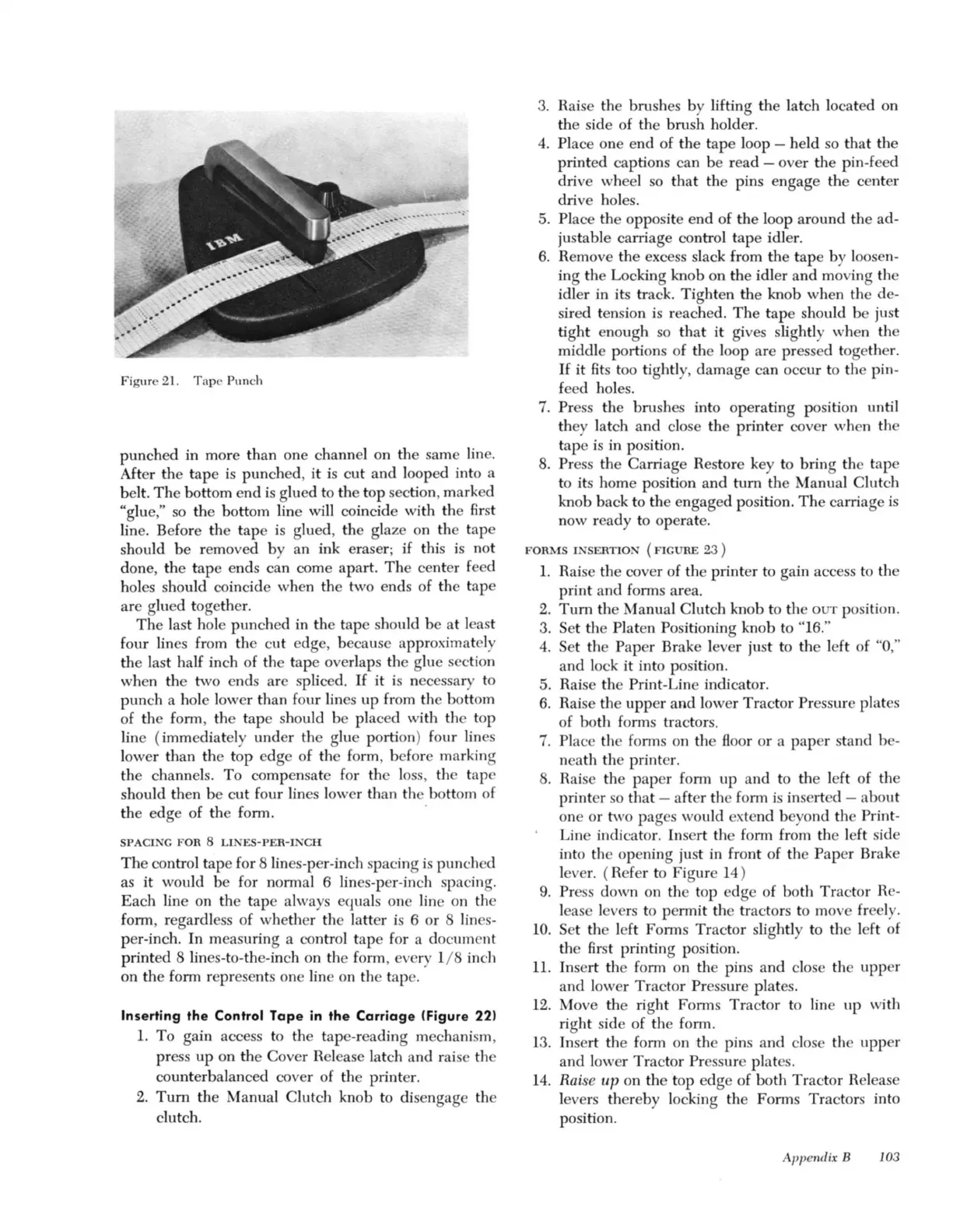
Figur
e 21.
Tap
e Punch
punched in more than one channel on the same lin
e.
After the tape
is
punched, it
is
cut and looped into a
belt.
Th
e bottom end
is
glued to the top section, mark d
"glue
,"
so
the bottom line will coincide with
th
e 6rst
lin
e.
Before the tape
is
glued, the glaze on the tape
should
be
removed by an ink eraser;
if
this
is
not
done, the tape ends can come apart. The ce
nt
er
fe
ed
hol
es
should coincide when the two ends of the tape
are g
lu
ed togethe
r.
Th
e last hole punched in the tape should be at least
four lin
es
from the c
ut
edge, because approximately
the last half inch of the tape overlaps the g
lu
e sec
ti
on
when the two ends are splice
d.
If
it is necessary to
punch a hole lower than fo
ur
lin
es
up from the bo
tt
om
of the form, the tape should be placed with the top
line (immediately under the g
lu
portion) four lin
es
lower than the top edge of the form, before marking
the channels. To compensate for the l
oss
, th tape
should then be cut four lin
es
lower than the bottom of
the edge of the form. .
SPACI
G F
OR
8
LINES-PER
-INC
H
Th
e control tape for 8 lin
es-
per-inch spacing
is
punched
as it would be for normal 6 lin
es-
per-inch spacing.
Each line on the tap always equals one line on the
form, regardl
ess
of whether the la
tt
er
is
6 or 8 lin
s-
per-inch. In measuring a
co
ntr
ol tape for a document
printed 8 lin
es-
t
o-
the-inch
on
the form, every 1/ 8
in
ch
on the form represents one line on the tape.
Inserting the Control
Tape
in the
Carriage
(Figure
22)
1.
To gain access
to
the tape-reading mechanism,
pr
ess
up on the Cover Release latch a
nd
raise the
counterbalanced cover of the printe
r.
2.
Tum
the Manual Clutch knob to disengage the
clutch.
3.
Raise the brush
es
by lifting the latch
lo
cated on
the side of the brush holder.
4.
Place one end of
the
tape loop - held
so
that the
printed captions can be read - over the pin-feed
drive wheel
so
that the pins engage the center
drive holes.
5.
Place th opposite end of the loop around the ad-
justable carriage control tape idler.
6. Remove
th
e excess slack from
th
e tape by loose
n-
ing the Locking knob on the idler
and
moving the
idler in its
tr
ack. Tighten
the
knob when the d
e-
sired tension is reached. The tape should be
ju
st
tight enough
so
that it gives s
li
ghtly when tlle
middle portions of the l
oo
p are
pr
essed togethe
r.
If
it
Rt
s t
oo
tightl
y,
damage can occur to the pin-
feed hol
es
.
7.
Pr
es
s tlle brushes into operating p
osi
ti
on until
they latch and close the printer cover when the
tape
is
in position.
8.
Pr
ess the Carriage Restore key to bring the tape
to its home position and
tum
the Manual Clutch
knob back to the engaged position. The carriage
is
now ready to operate.
F
ORMS
I
NSE
RTIO
N
(FIGURE
23 )
1.
Raise the cover of the printer to gain access to the
print and fonns area.
2.
Tum
the Manual Clutch knob to the
OUT
p
osi
ti
on.
3.
Set the Plat n Positioning knob to "
16.
"
4. Set the Paper Brake lever just to the left of "0
,"
and lock
it
into p
os
ition.
5.
Raise the Print-Line indicator.
6. Raise the upper a
nd
lo
wer Tractor
Pr
essure plates
of both forms tractors.
7.
Place the forms
on
the
Boor
or a
pap
er stand b -
neath the printe
r.
8.
Ra
is
e the
pap
er form up and to the left of the
printer
so
that - after th form
is
inserted - about
one or two
pag
es
would
ex
tend beyond the Print-
Line indicato
r.
Insert the form from the left side
into th open
in
g just in front of the Paper Brake
leve
r.
(Refer to Figure 1
4)
9.
Pr
ess down on the top edge of both
Tr
actor Re-
lease leve
rs
to permit tlle tractors to move freel
y.
10.
Set the left Forms
Tr
actor slightly to th 1
ft
of
the
Rr
st printing position.
11.
In
se
rt the form on the pins and close the upper
and
lower Tractor Pressure plat
es.
12.
Move the right Forms Tractor to line up with
rig
ht
side of the form.
13
. Insert the form on the pins and close the upper
and lower Tractor
Press
ur
e plat
es.
14.
Rai
se
up
on the top edge of both Tractor Release
leve
rs
thereby locking the Forms Tractors into
position.
Appendix B 103