Plinch Check Lig
ht
.
The
punch
check
li
g
ht
is turncd
on
wh
n there
is
an un
qual
comparison be
tw
ecn the
data
punch
ed
and
the
data
r
ea
d (one
card
f ed cycle
l
ater
,
at
the
check
station),
or
wh
en a 1622
parit
y error
occurs
during
punching
(se
lect stop switch set to
STOP).
Th
e
ma
hine stops,
and
r
ady
status is terminated.
Chip
Li
gl!t.
Th
chip
li
g
ht
is turned on to indicate
that
the
chip
box should be emptied.
1620 Con
so
le
Writ
e Ch eck
Li
ght.
Th
e 1620
writ
check (
07
) indicator
and
consol Ii
ht
ar
turn d on
by a
parit
y
ITor
durin
g a core to rag to huffer stor
ag
transfe
r.
Th
07
indicator
ma
y be
pr
ogrammed to trans-
fer
dat
a several times
and
to
halt
if a corr ct
tr
ansfer
cannot
be
ohtain
ed.
1620 Con ole Pllnch 0 Feed
Li
ght.
Th
e co
nsok
punch
no f
ee
d light is turned on
eac
h timc thc
pun
ch
is selccted
by
a
writ
e co
mmand
.
Th
c
li
g
ht
remains on
until the
pun
ch
unit
is r
ea
dy
and
exec
ut
es the com-
mand
. 10rmal\y,
no
li
g
ht
is seen if co
mmand
s arc
further
apart
than
480
millisccond
s.
Th
e write com-
mand
cann
ot
b xecuted until the
pun
ch is in rea
d:-
,
status.
C
HO
H
EADEn
/ P :\'C H LIG
HT
S
Th
e stacker, h'an
port
, fuse,
and
th rma
lli
ghts
ar
c used
commonly b
both
the
I'
ad
and
punch
fceds
as
fol\ows:
Stacker
Li
ght.
Th
e stacker
li
g
ht
is turned on
when
a
stac
ker is full. Both feeds ar s
topp
ed tc
mp
orarily a
nd
I'
moved from re
ad
statu.
Th
r
ea
dy
li
g
ht
remains on.
Op
ration resumes
automatica
ll
y
after
the stacker
is
mptied.
Transport
Li
g
ht
.
Th
e
transport
li
g
ht
is
turn
ed on
when
a
card
jam has occurred in either th read or
punch
feed or above any tacke
r.
\\
h n this
occur
s,
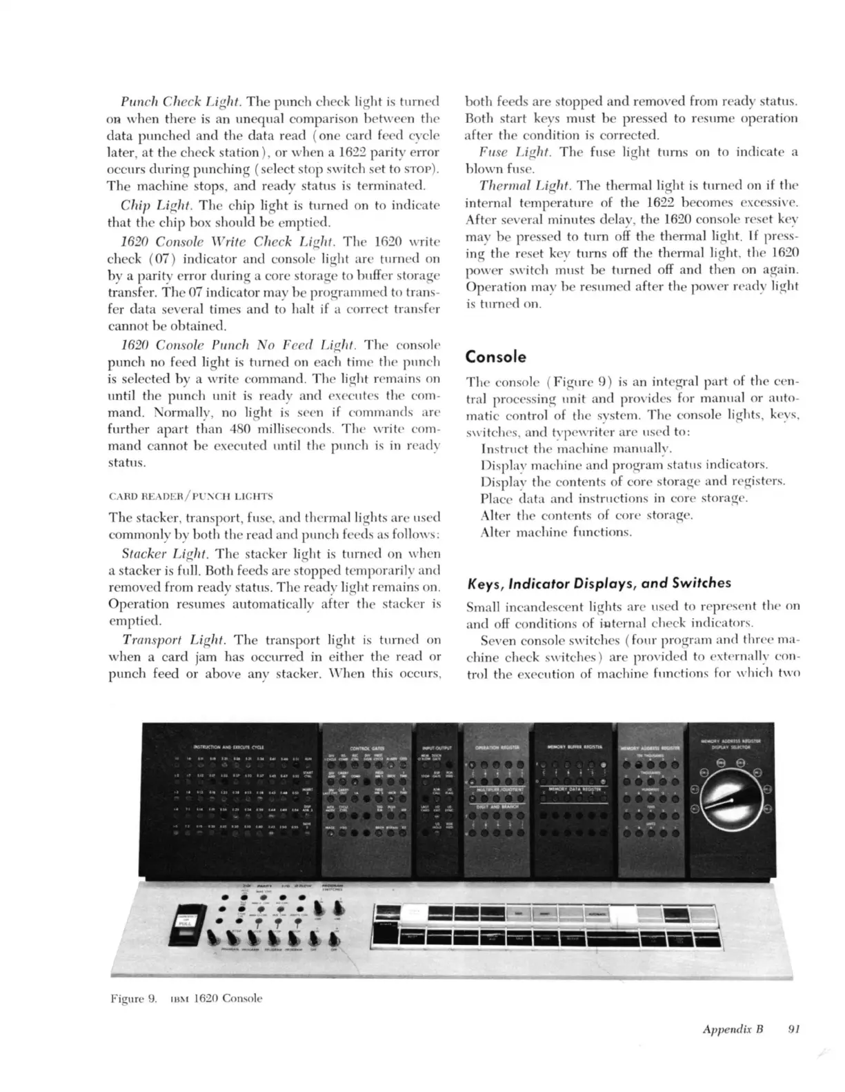
Figure
9.
113~1
1620 Console
both
f d
are
sto
pp
ed
and
r moved from r
ad
statu
s.
Both sta
rt
keys
must
be
pr
ess d to resume operation
after th condition is corr ted.
Fli
se Light.
Th
e fuse
li
g
ht
turns on to indicate a
hl
own fus .
Th
ermal
Li
g
ht
.
Th
e th
rmalli
g
ht
is
turn
ed on if the
int
ernal t
mp
er
atur
of the 1622 becomes excessiv .
Aft
I'
several
minut
es delay, th 1620 onsole
I'
set key
may b
PI'
sed to
turn
off th thermal
li
ght.
1£
pr
ess-
ing
the r s t k Y turns off the th rmal
li
ght. the 1620
power s
wit
ch must be turn d off
and
th n on
aga
in.
Op
ration may be r Slimed
after
the power ready
li
ght
is tllrn
ed
on.
Console
Th
e consol ( Figur
9)
is
an
int
eg
ral
part
of the cen-
tral
pr
ocessing
unit
a
nd
pro id s for manual or
auto
-
matic control of the system.
Th
e con. ole
li
ghts, keys,
switch s, a
nd
t:'p
ew
ritcr
are
used to:
In
st
ruct th
ma
chine manua
ll
y.
Dis
pla:-
' m
ac
hine and program status indi ator
s.
Di
splay the co
nt
e
nt
s of core storage and r
eg
iste
rs
.
Place
data
and
instructions
in
core storage.
A Iter the co
nt
e
nt
· of core storag
e.
Alter machine function
s.
Keys, Indicator Displays,
and
Switches
ma
ll
inca
nd
sce
nt
li
g
ht
s arc used to
I'
pr
ese
nt
the on
and
off conditions of
i~t
e
rnal
check
in
li
cator
s.
Seven console switche. (four program and three ma-
chin check switche )
are
prO
Vided to extcrna
lJ:-
,
'o
n-
trol the xecution of machine func
ti
ons for which two
App
endix B
91