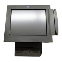
Reset switch
A pin hole reset switch is provided on the MSR unit in a location not accessible when the MSR is fully
installed. When the user presses this switch the MSR configuration word stored in flash is changed back to
the factory default and the unit restarts. The configuration word in RAM is replaced by the new flash word
when the MSR restarts.
The JUCC reader will communicate via the 2-wire serial interface only and there should not be a slide switch
on the JUCC MSR.
Command Set
The commands sent to the MSR will be used to either configure the format and features of the MSR return
data or to update the MSR firmware. No changes to the configuration are permanent until a commit
command is sent. This means that configuration word changes will be lost at power off unless they are
committed.
Control commands
All command strings to the MSR are to be in the following format:
MSR command: “:nnxxxx11cc[dd]{0,16}ss”
nn: one byte hexadecimal number representing number of command and data bytes in command
string, value between 0x00 and 0x10.
xxxx: four byte address used in memory commands, not used and should be considered don’t care.
cc: hexadecimal command value between 0 to 127 return values are 128 to 255.
dd: 0 to 16 data bytes in hexadecimal format associated with the command.
ss: checksum, negative of the sum of the values in the command string. Summing all the hex values
in the command string including the checksum should equal zero.
All commands except the “get configuration” commands will only be followed by a fail/success response. The
success response will be “.” and the fail response will be “X”. Characters sent to the MSR are to be repeated
back to the host as they are received. The use of upper and lower case letters are can be used in the
hexadecimal numbers.
The MSR response to the “get configuration” command will be formatted as:
:nn0000117F <b1><b2><b3><b4><b5><revision string[11]>
nn: number of data bytes; b1 through b5 plus the length of the revision string.
bx: hexadecimal number representing bytes 1 through 5 of the configuration word .
revision string: Up to 11 byte long description string showing firmware revision information.
Suggested format is “REV x.xx.”
An example would be the command to enter command mode, “:0100001110.” This shows the “:nn000011”
preamble, the hexadecimal command byte “10” and a byte count of 01. The MSR would respond with the
character ‘.’ to indicate a successful command.
SurePOS 500 Model XX3 Technical Reference, v 1.3 Page 72 of
81

 Loading...