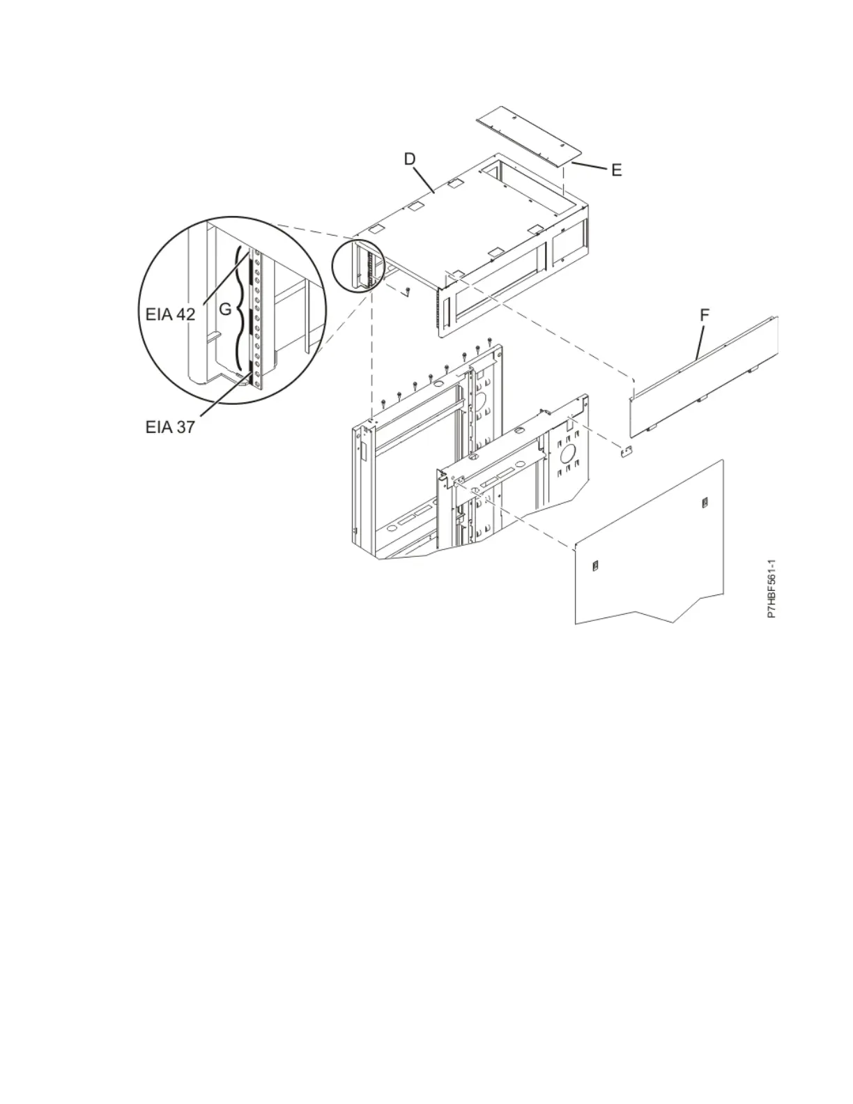
2. Install the six screws at the left and right sides of the rack top cover. The screws are installed inside
the three small rectangular openings on each side of the rack top cover.
Item Description
D Top cover
E Cable access cover
F Side cover (quantity 2)
G EIA label
Figure 67. Replacing the top cover
Note: A 10 mm 6 point (pt) box socket with an extension bar is required to replace the screws into the
rack top cover. Other tools might cause the screw heads to become rounded and unable to be
removed again.
3. Remove the rack braces (A) and (C) by unfastening them at the top of the rack, just below the top
cover. Remove the braces at the front and rear of the rack.
96
Power Systems: Racks and rack features
 Loading...