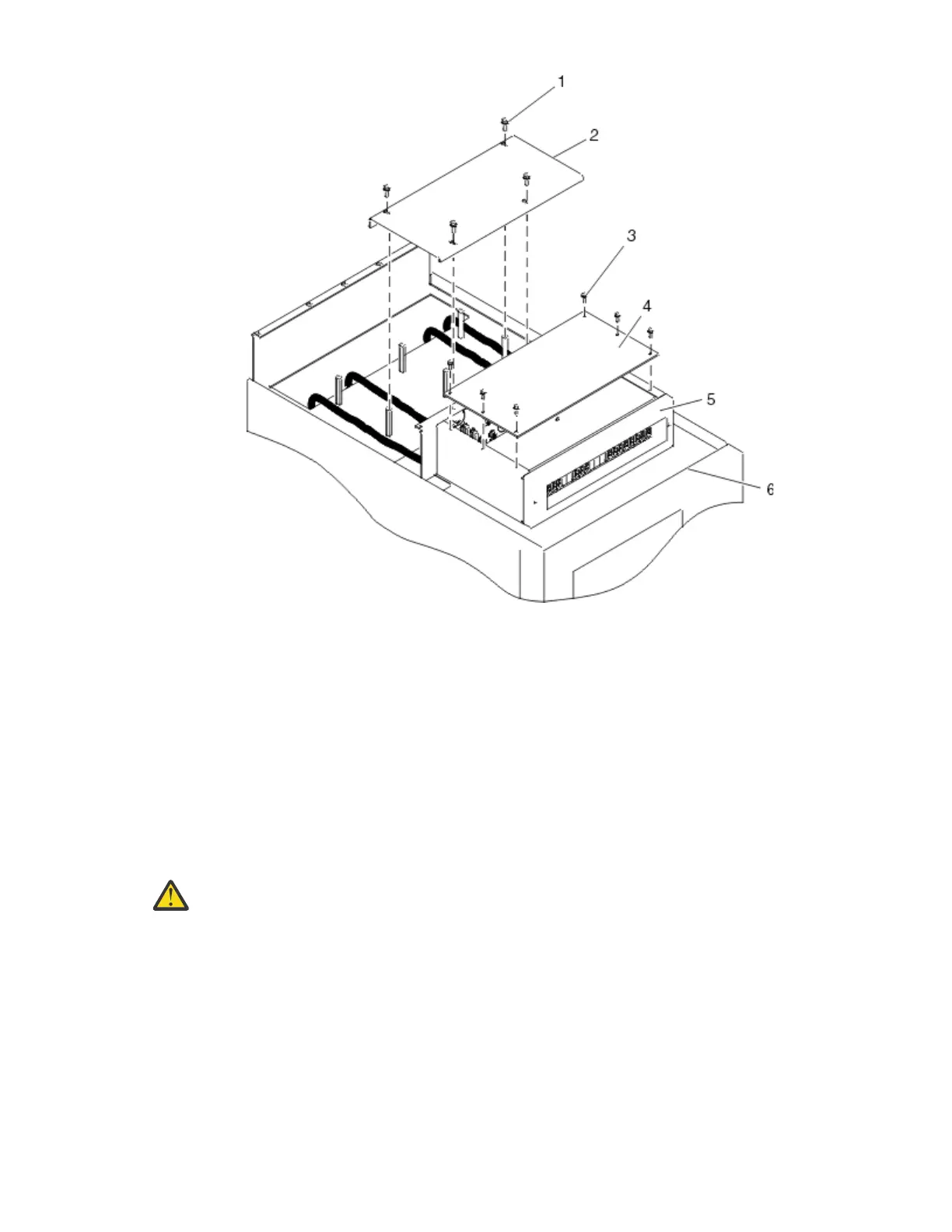
Figure 30. Removing the cable channel cover
Item
Description Item Description
1 Cable channel cover retaining
screw
5 Shield
2 Cable channel cover 6 Power distribution panel
3 Power distribution panel top
cover retaining screws
4 Power distribution panel top
cover
3. Remove the -48 V DC bus bar shield from the power distribution panel.
DANGER:
The bus bar shield must be correctly reinstalled over the -48 V DC return bus bars to
protect against injury while servicing the power distribution panel.
4. Ensure that the following steps are performed when connecting the DC power source.
a. At -48 V DC power source, turn off any -48 V DC power sources that will be connected to the power
distribution panel.
b. After the -48 V DC power sources are turned off, be sure there is a tag or label over the power
source switches or fuses (lock-out/tag-out) to indicate that the power source is turned off
intentionally.
Note: Ensure that any oxidation on the copper bus bars is removed.
c. If this is a raised-floor installation and you are working at the rear of the rack, route the power
cables up the rack's right side.
d. Ensure that the external -48 V DC power cable is connected correctly to the -48 V DC bus bar.
Racks and rack features
45
 Loading...