e. Ensure that the external -48 V DC return cable is routed correctly and installed on the return bus
bar.
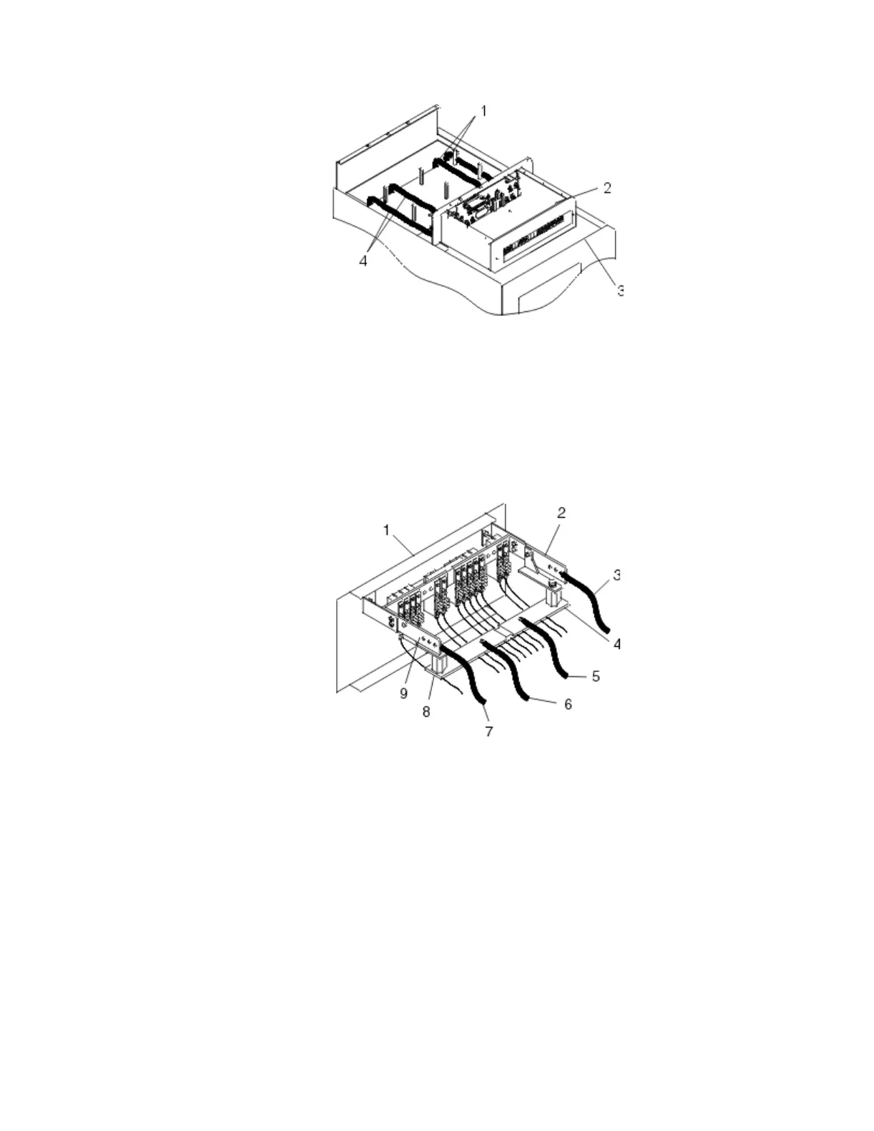
Figure 31. Routing the power cables
Item Description
1 -48 V DC power cable and return power cable
2 Power distribution panel
3 Front of rack
4 -48 V DC power cable and return power cable
Figure 32. Return bus bar
Item
Description Item Description
1 Front of power distribution
panel
6 (B) Return (-) power cable
2 (A) -48 V DC (-) bus bar 7 (B) -48 V DC (-) power cable
3 (A) -48 V DC (-) power cable 8 (B) Return (-) bus bar
4 (A) Return (-) bus bar 9 (B) -48 V DC (-) bus bar
5 (A) Return (-) power cable
f. If you want to install a power status alarm, connect the alarm cable to the terminal board on the
rear cover of the DC power distribution panel.
Note: Ensure that you remove the oxidation on the copper bus bars.
g. Ensure that the power-source ground cable is routed correctly and connects the power-source
ground cable to the copper bar at the lower-rear or upper-rear center of the rack.
46
Power Systems: Racks and rack features
 Loading...