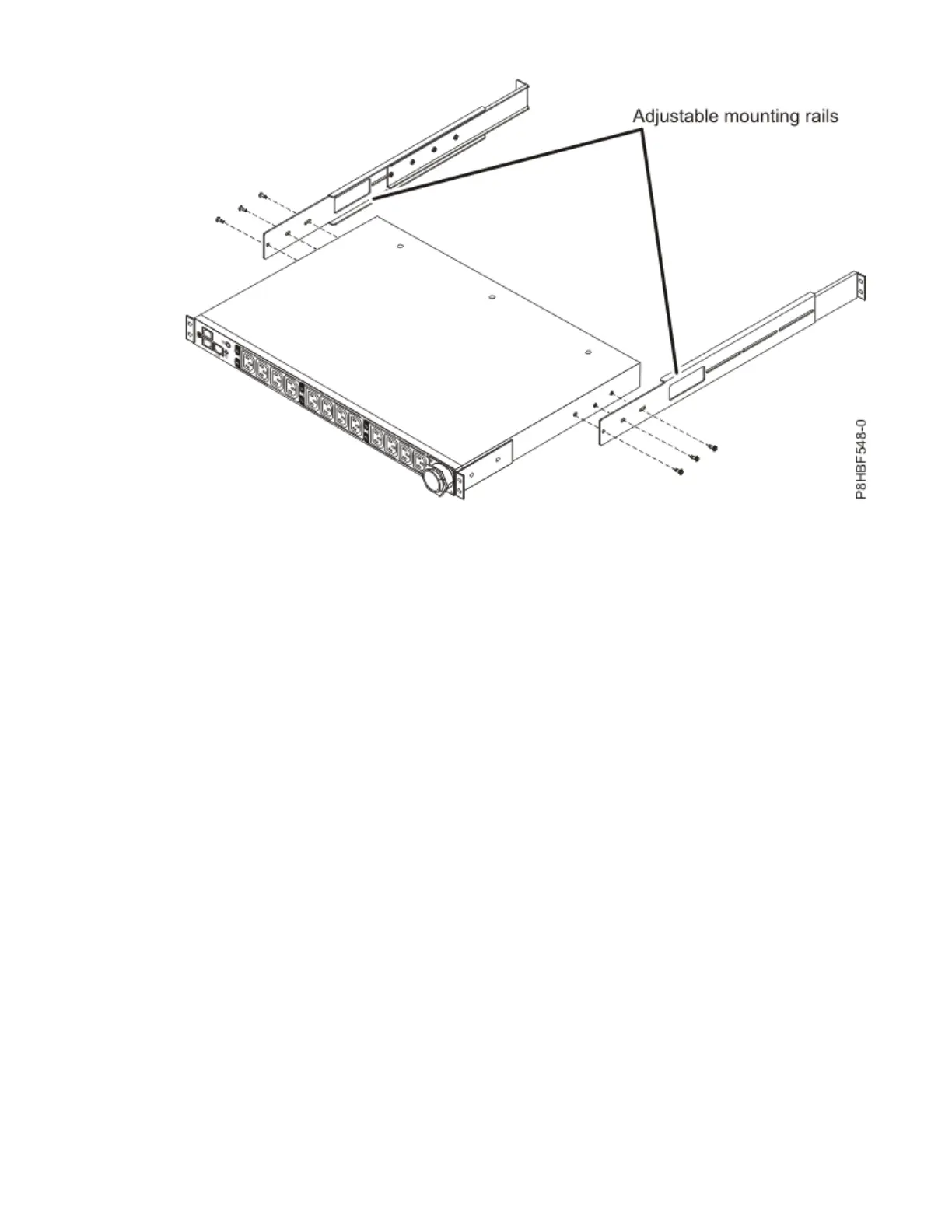
Figure 43. Attaching the adjustable mounting rails to the Intelligent Switched PDU chassis
9. Identify an open mounting space that is the size of a single EIA in the rack where you are installing
the PDU model.
At the rear of the rack, attach nut clips to the top and bottom holes of the EIA on each side of the
rack. Use nut clips that were provided with the rack mounting kit.
Note: If your rack has square mounting holes, attach cage nuts instead of nut clips to the specied
EIA locations. Use cage nuts that were provided with the rack mounting kit.
10. Hold the PDU model at a slight angle and carefully insert it into a mounting space that is a single EIA
unit within the rack cabinet. Pushing in slightly on both of the long mounting brackets helps clear the
brackets from the rack flanges.
11. Align the end of the PDU model with the short mounting brackets with the outside of the rack flanges.
Use two M6 screws (A) if cage nuts are used or M5 screws if nut clips are used per bracket to attach
the brackets to the nut clips or cage nuts on the rack flanges. Use screws that were provided with the
rack mounting kit.
60
Power Systems: Racks and rack features
 Loading...