correctly located, remove the lower plastic isolator bushings.
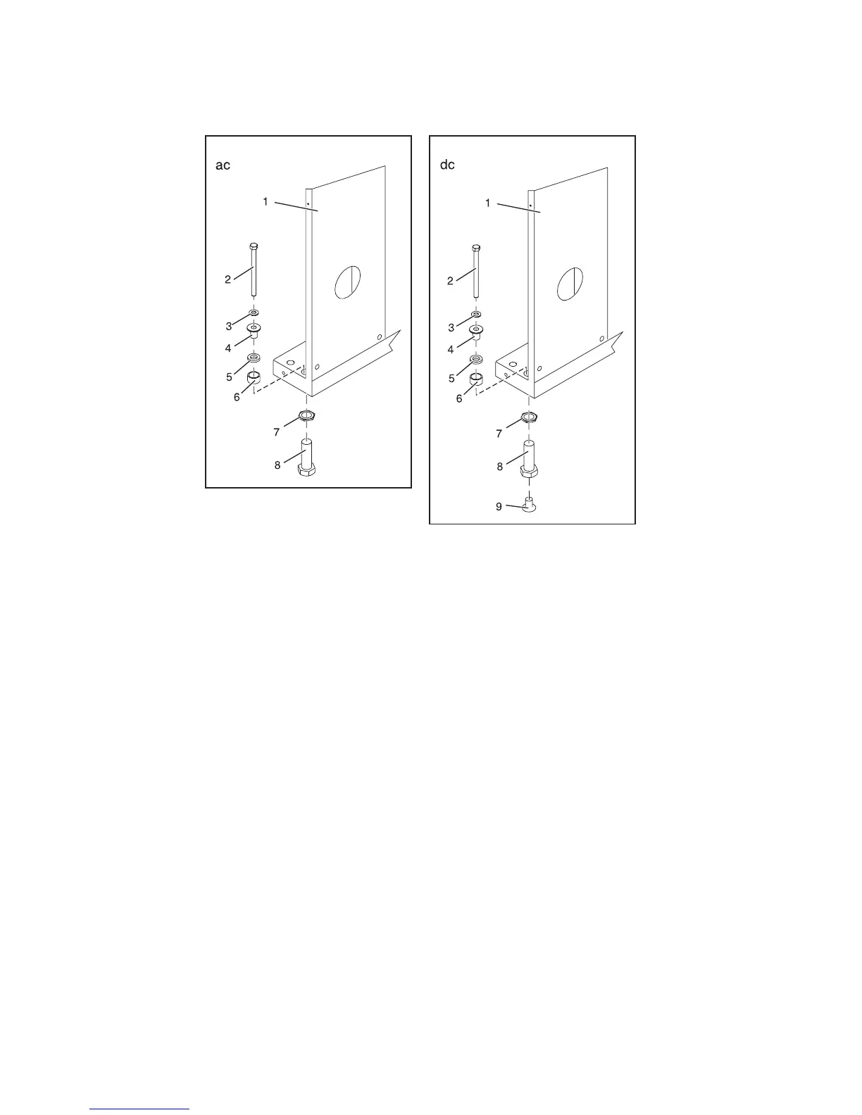
1 Rack chassis 7 Jam nut
2 Rack-mounting bolt 8 Leveling foot
3 Thin washer 9 Lower plastic isolator bushing (used
only on dc powered systems)
4 Top plastic isolator bushing ac Typical leveling foot installation for
an ac-powered rack
5 Thick washer dc Typical leveling foot installation for
an dc-powered rack
6 Spacer
6. Position the two mounting plates in the approximate mounting location under the rack.
7. Create a rack-mounting bolt assembly by adding the following items, in the order listed, to each
rack-mounting bolt.
a. Thin washer
b. Top plastic isolator bushing
c. Thick flat washer
d. Spacer
8. Insert a rack-mounting bolt assembly through each of the leveling feet.
9. Reposition the rack-mounting plates under the four rack-mounting bolts so that the mounting bolts
are centered directly over the threaded bolt holes.
10. Turn the rack-mounting bolts four complete turns into the mounting plate's threaded bolt holes.
Figure 5. Installing ac-power mounting plates
6 Power Systems: Racks and rack features
 Loading...