v Remove the server battery and then reinstall it. See “Battery” on page 32 for
instructions for removing the battery.
v Change the position of the power-on password override jumper (J9 on the I/O
board) to bypass the power-on password check.
Attention: Before changing any switch settings or moving any jumpers, turn off
the server; then, disconnect all power cords and external cables. See the safety
information beginning on page vii. Do not change settings or move jumpers on
any system-board switch or jumper blocks that are not shown in this document.
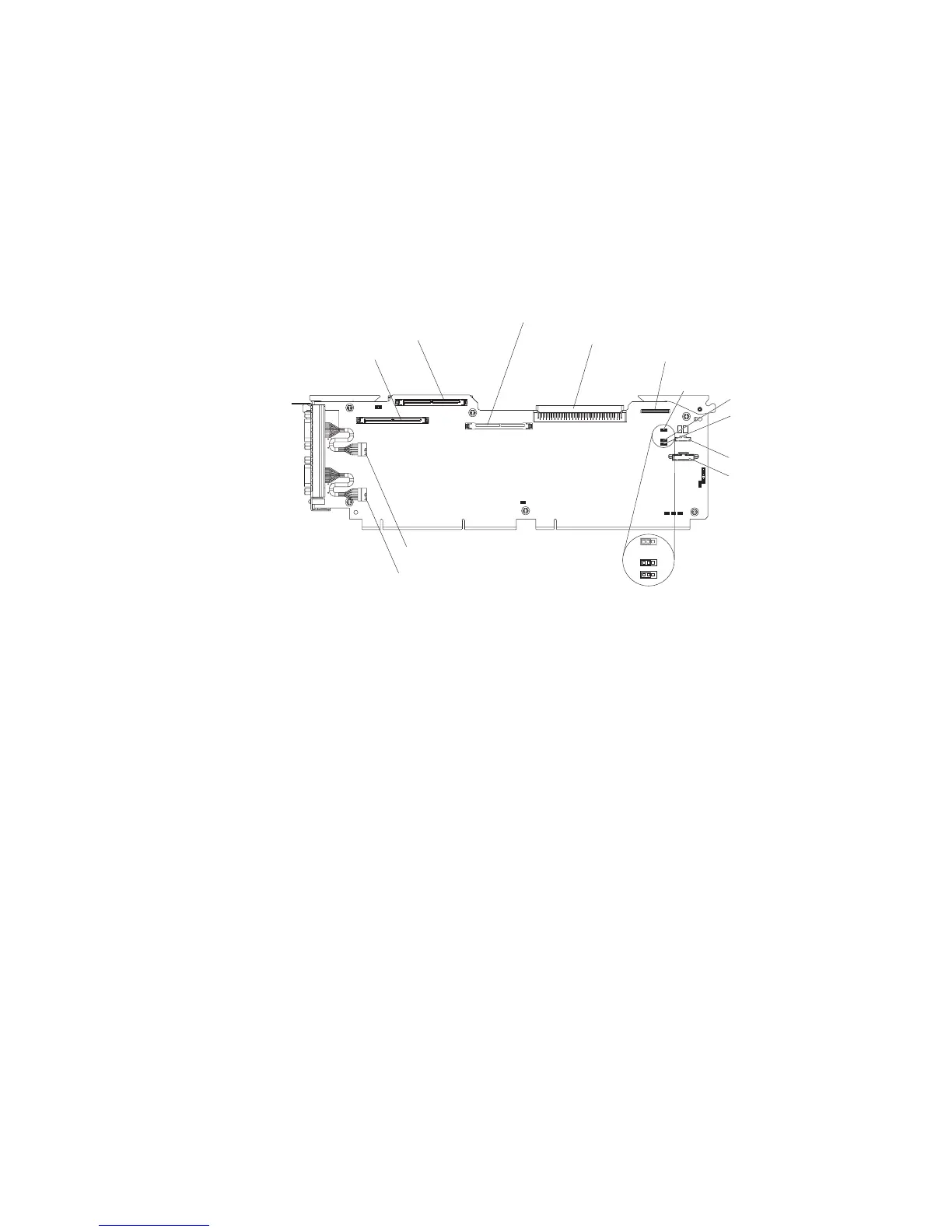
The following illustration shows the location of the power-on password override,
boot recovery, and Wake on LAN (WOL) bypass jumpers.
Light path diagnostic
Front USB
Battery
Power-on password
override
Boot recovery
Wake-on-LAN
bypass
Media backplane
Remote Supervisor Adapter II SlimLine
SAS 1
SAS 2
SP serial (COM 2)
System serial (COM 1)
123
123
123
Default jumper
position
While the server is turned off, move the jumper on J9 from pins 1 and 2 to pins 2
and 3. You can then start the Configuration/Setup Utility program and reset the
power-on password. After you reset the password, turn off the server again and
move the jumper back to pins 1 and 2.
The power-on password override switch does not affect the administrator
password.
Administrator
password: If an administrator password is set, you must type the
administrator password for access to the full Configuration/Setup Utility menu. You
can use any combination of up to seven characters (A–Z, a–z, and 0–9) for the
password. The Administrator Password choice is on the Configuration/Setup
Utility menu only if an optional IBM Remote Supervisor Adapter II SlimLine is
installed.
Attention: If you set an administrator password and then forget it, there is no way
to change, override, or remove it. You must replace the I/O board.
Installing and using the baseboard management controller utility
programs
The baseboard management controller provides environmental monitoring for the
server. If environmental conditions exceed thresholds or if system components fail,
the baseboard management controller lights LEDs to help you diagnose the
problem and also records the error in the System Event/Error log.
Also use the baseboard management controller to establish a Serial over LAN
(SOL) connection to manage servers from a remote location. You can remotely view
Chapter 2. Configuration information and instructions 19
 Loading...


