2. Connect the light path diagnostics ribbon cable and front USB cable to the I/O
board.
3. Slide the front-panel assembly into the server until the blue tab on the chassis
engages.
4. Replace the bezel and top cover.
5. Reconnect external cables and power cords.
I/O board
When replacing the I/O board, you must either update the server with the latest
SAS firmware or restore the pre-existing firmware from a diskette or CD image.
The I/O board contains three-pin jumper blocks. See “I/O board internal connectors
and jumpers” on page 8 for the location and description of each jumper block.
Replacing the I/O board
To remove the I/O board, complete the following steps.
1. Read the safety information that begins on page vii, and “Handling
static-sensitive devices” on page 31.
2. Turn off the server and peripheral devices, and disconnect the power cords and
all external cables necessary to replace the device.
3. Remove the top cover.
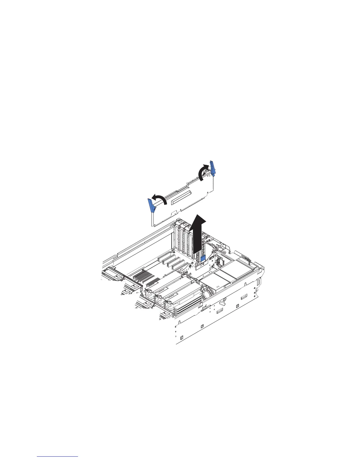
Attention: When moving the I/O board, do not allow it to impact any
components or structures inside the server.
4. Open the release latches on both ends of the I/O board and pull the board from
the server slightly.
Chapter 4. Removing and replacing server components 49
 Loading...


