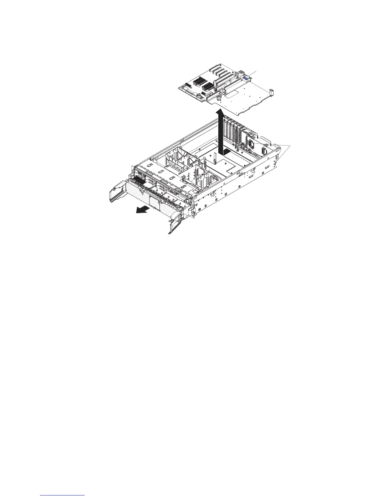
PCI board assembly
Complete the following steps to remove a PCI board assembly.
AC
D
C
Retainer
screws
Handle
1. Read the safety information that begins on page vii, and “Handling
static-sensitive devices” on page 31.
2. Turn off the server and peripheral devices, and disconnect the power cords
and all external cables necessary to replace the device.
3. Remove the top cover and bezel (see “Removing the cover and bezel” on
page 31).
4. Remove the power supplies and power-structure assembly (see “Power-supply
structure” on page 51).
5. Remove the I/O board (see “I/O board” on page 49).
6. Remove all adapters and adapter dividers, and place the adapters on a
static-protective surface.
Note: You might find it helpful to note where each adapter is installed before
removing the adapters.
7. Disconnect the PCI switch card cable from the PCI board (see “PCI switch
card assembly” on page 60).
8. Disconnect the SAS backplane power cable from the PCI board (see “SAS
backplane” on page 53).
9. Remove all fans (see “Hot-swap fan” on page 34).
10. Remove the memory cards (see “Removing and replacing a memory card” on
page 41).
11. Lift the microprocessor-tray release latch, open the microprocessor-tray levers,
and pull the microprocessor tray out of the server slightly (see “Removing and
installing a microprocessor” on page 55).
12. Remove the power backplane (see “Power backplane” on page 61).
13. Loosen the blue retainer screws on the rear of the server.
Chapter 4. Removing and replacing server components 59
 Loading...


